Engine General Information and Diagnosis: 1A-146
DTC P0480: Fan 1 (Radiator Cooling Fan) Control Circuit
S5JB0A1104048
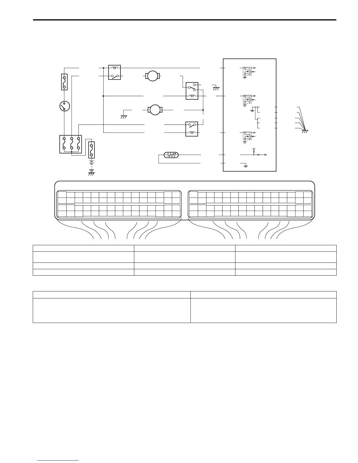
Wiring Diagram
DTC Detecting Condition and Trouble Area
DTC Confirmation Procedure
1) Turn OFF ignition switch.
2) Clear DTC with ignition switch turned ON.
3) Run engine at idle speed.
4) Check DTC.
E23 C37
34
1819
5671011
1720
47 46495051
2122
52
1625
9
24
14
29
5557 54 53
59
60 58
2
262728
15
30
56 48
32 31343536374042 39 38
44
45 43 41 33
11213
23
834
1819
5671011
1720
47 46495051
2122
52
1625
9
24
14
29
5557 54 53
59
60 58
2
262728
15
30
56 48
32 31343536374042 39 38
44
45 43 41 33
11213
23
8
5V
RED/BLK
E23-46
E23-47
BLU/RED
BLU/YEL
BLU/BLK
E23-48
PPL/YEL
GRY/GRN
C37-24
C37-57
1
2
10
3
4
8
5
9
BLK
RED
YEL/GRN
C37-15
C37-29
C37-48
BLK/ORN
C37-58
C37-30
BLK/ORN
BLK/YEL
BLK/YEL
BLK/YEL
RED/YEL
BLK
BLU
BLU
YEL/GRN
BLU/WHT
YEL/GRN
6
7
I5JB0A110056-01
1. Fuse box No.2 5. Radiator cooling fan relay No. 3 9. ECT sensor
2. Ignition switch 6. Radiator cooling fan motor No.1 10
.
“IG2 SIG” fuse
3. Radiator cooling fan relay No. 1 7. Radiator cooling fan motor No.2
4. Radiator cooling fan relay No. 2 8. ECM
DTC detecting condition Trouble area
Monitor signal of radiator cooling fan relay is different from
command signal.
(1 driving cycle detection logic)
• Radiator cooling fan relay circuit malfunction
• Radiator cooling fan relay malfunction
• ECM malfunction

 Loading...


