Engine General Information and Diagnosis: 1A-130
DTC P0340: Camshaft Position (CMP) Sensor Circuit
S5JB0A1104041
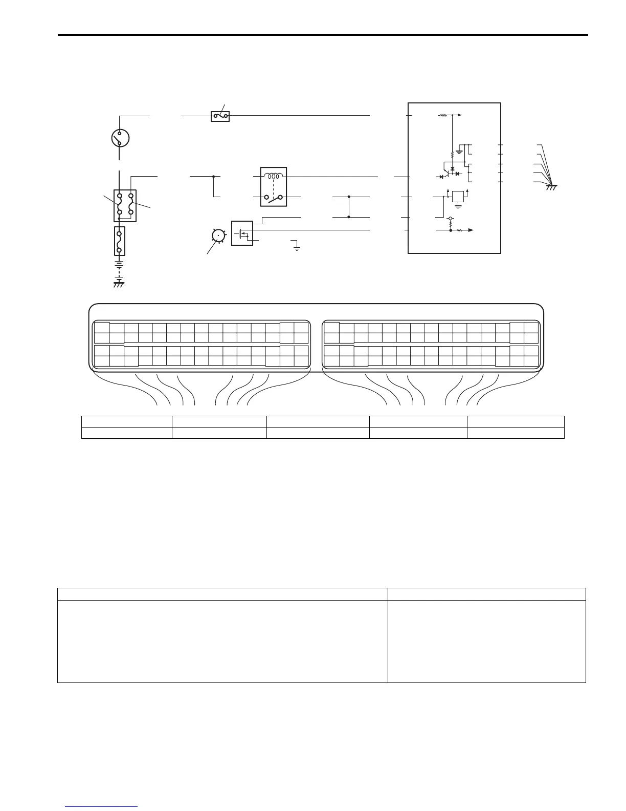
Wiring Diagram
System Description
The CMP sensor located on the transmission side of cylinder head (for M16 engine) or cylinder head cover (for J20
engine) consists of the signal generator (magnetic sensor) and signal rotor (intake camshaft portion).
The signal generator generates reference signal through slits in the slit plate which turns together with the camshaft.
Reference signal
The CMP sensor generates 6 pulses of signals each of which has a different waveform length while the camshaft
makes one full rotation. Refer to “Inspection of ECM and Its Circuits: ”.
Based on these signals, ECM judges which cylinder piston is in the compression stroke and the engine speed.
DTC Detecting Condition and Trouble Area
DTC Confirmation Procedure
1) With ignition switch turned OFF, connect scan tool.
2) Turn ON ignition switch and clear DTC using scan tool.
3) Crank engine for 5 sec.
4) Check DTC and pending DTC.
E23 C37
34
1819
5671011
1720
47 46495051
2122
52
1625
9
24
14
29
5557 54 53
59
60 58
2
262728
15
30
56 48
32 31343536374042 39 38
44
45 43 41 33
11213
23
834
1819
5671011
1720
47 46495051
2122
52
1625
9
24
14
29
5557 54 53
59
60 58
2
262728
15
30
56 48
32 31343536374042 39 38
44
45 43 41 33
11213
23
8
12V
5V
BLU/BLK
BLU/BLK
BLK/RED BLK/RED
BLK/RED
BLU
5
6
4
8
3
E23-29
E23-1
E23-60
7
E23-16
1
C37-52
5V
BLK/YEL
BLK/WHT
9
WHT/GRN
2
WHT/RED
BLU/BLK
BLU/BLK
BLK/YEL
C37-15
C37-29
C37-48
BLK/ORN
C37-58
C37-30
BLK/ORN
BLK/YEL
BLK/YEL
BLK/YEL
I5JB0A110049-01
1. CMP sensor 3. ECM 5. Ignition switch 7. “FI” fuse 9. “IGN” fuse
2. Signal rotor 4. Main relay 6. Fuse box No.2 8. “IG COIL” fuse
DTC detecting condition Trouble area
• CMP sensor pulse is less than 20 pulses per crankshaft 8 revolutions
• CMP sensor pulse is more than 28 pulses per crankshaft 8 revolutions
• CMP sensor pulse is less than 20 pulses between BTDC 155° crank
angle (for M16 engine) or BTDC 75° crank angle (for J20 engine) and
BTDC 5° crank angle with crankshaft 8 revolutions from engine start.
(1 driving cycle detection logic)
• CMP sensor circuit open or short
• Signal rotor teeth damaged
• CMP sensor malfunction, foreign
material being attached or improper
installation
•ECM

 Loading...


