5A-24 Automatic Transmission/Transaxle:
DTC Clearance Using Monitor Connector (If
Equipped)
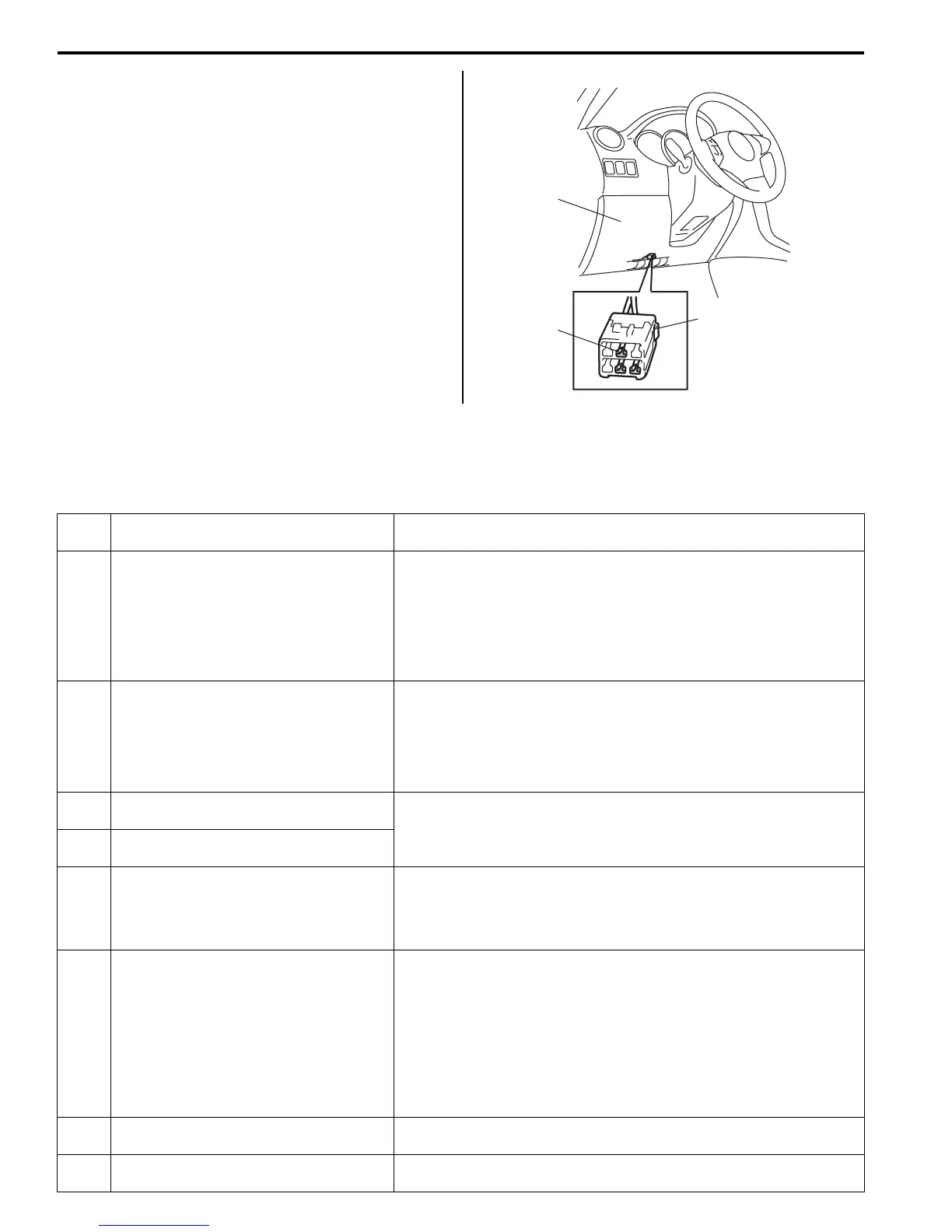
1) Remove steering column hole cover (1).
2) Turn ignition switch ON.
3) After 6 seconds or more, repeat connecting and
disconnecting diagnosis switch terminal (3) of
monitor connector (2) and body ground 5 times at
about 1 second interval within 10 seconds, using
service wire.
4) Check TCM that no malfunction DTC remains in
memory of it.
Fail Safe Table
S5JB0A5104008
This function is provided by the safe mechanism that assures safe driveability even when the solenoid valve, sensor or
its circuit fails. The following table shows the fail safe function for each fail condition of sensor, solenoid, TCM or its
circuit.
3
1
2
I5JB0A510017-01
DTC
No. Trouble Area Fail Safe Operation
)P07
05
Transmission Range Sensor Circuit
Malfunction (PRNDL Input)
• TCM control is performed in priority order below.
3> D> 2> L> R> N> P
• Slip controlled lock-up function is inhibited to operate.
• Reverse control is inhibited.
• Cruise control function is inhibited to operate.
• Power mode is inhibited.
)P07
07
Transmission Range Sensor Circuit Low • Range is assumed to be “D” range.
• Slip controlled lock-up function is inhibited to operate.
• Reverse control is inhibited.
• Cruise control function is inhibited to operate.
• Power mode is inhibited.
)P07
12
Transmission Fluid Temperature Sensor
“A” Circuit Low
• A/T fluid temperature is assumed to be 80 °C (176 °F).
• Lock-up function is inhibited to operate.
• Line pressure control at gear shifting is inhibited.
)P07
13
Transmission Fluid Temperature Sensor
“A” Circuit High
)P07
17
Input / Turbine Speed Sensor Circuit No
Signal
• Torque reducing request to ECM (torque reduction control) is
inhibited.
• Lock-up function is inhibited to operate.
• Line pressure control at gear shifting is inhibited.
)P07
22
Output Speed Sensor Circuit No Signal • Vehicle speed which is calculated by input shaft speed sensor
signal is used for gear shifting control instead of vehicle speed
calculated by output shaft speed sensor (VSS) signal.
• Upshifting to 4th gear is inhibited.
• Lock-up function is inhibited to operate.
• Torque reducing request to ECM (torque reduction control) is
inhibited.
• Line pressure control at gear shifting is inhibited.
)P07
42
Torque Converter Clutch Circuit Stuck
On
When vehicle speed is less than 10 km/h (6 mile/h), gear position is
fixed in 1st gear for prevention of engine stall.
)P07
52
Shift Solenoid “A” Stuck On Upshifting to 4th gear is inhibited.

 Loading...


