1A-115 Engine General Information and Diagnosis:
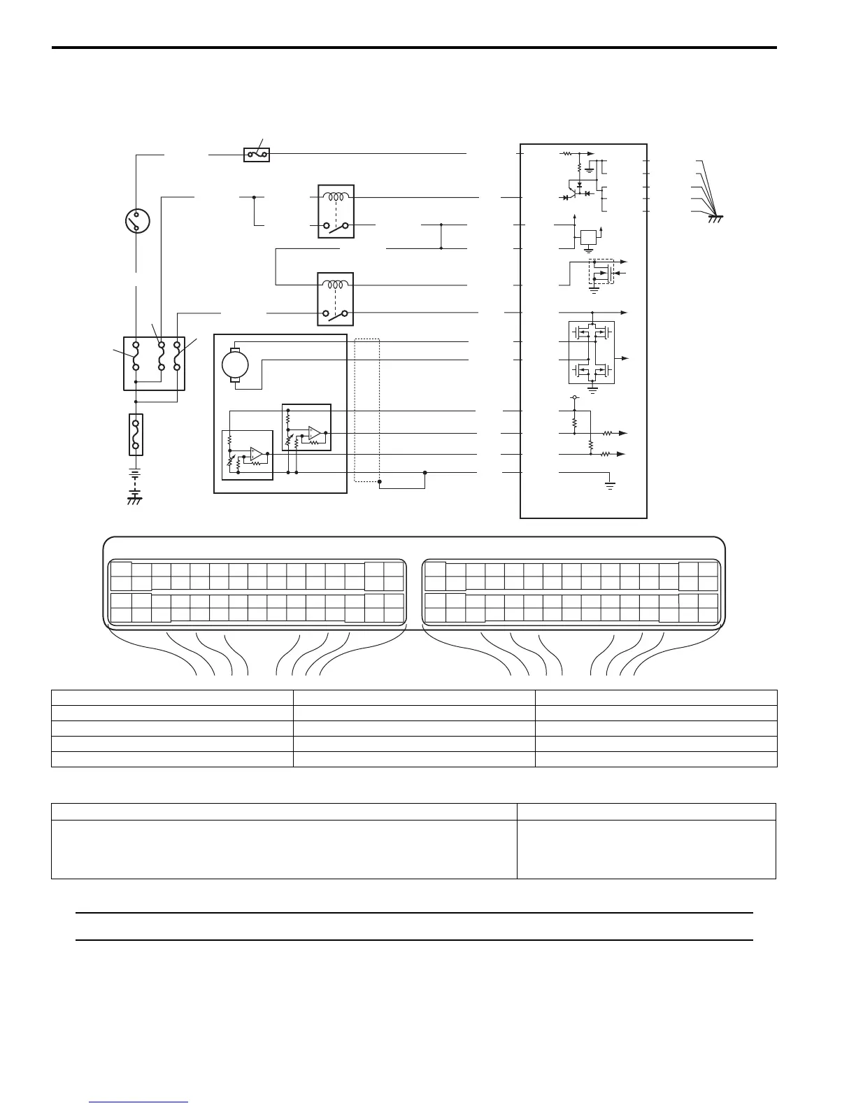
DTC P0222: Throttle Position Sensor (Sub) Circuit Low
S5JB0A1104075
Wiring Diagram
DTC Detecting Condition and Trouble Area
NOTE
When DTC P0122 and P0222 are indicated together, it is possible that “WHT” wire open circuit.
E23 C37
34
1819
5671011
1720
47 46495051
2122
52
1625
9
24
14
29
5557 54 53
59
60 58
2
262728
15
30
56 48
32 31343536374042 39 38
44
45 43 41 33
11213
23
834
1819
5671011
1720
47 46495051
2122
52
1625
9
24
14
29
5557 54 53
59
60 58
2
262728
15
30
56 48
32 31343536374042 39 38
44
45 43 41 33
11213
23
8
12V
5V
BLU/BLKBLU/BLK
BLK/RED
1
2
BLK/RED
BLK/RED
BLU
E23-1
E23-60
C37-15
C37-29
C37-48
BLK/ORN
C37-58
BLU/ORN
GRN
BLU/RED
BLU/YEL
BLU/RED
E23-16
E23-50
E23-17
C37-45
C37-44
1-1
1-2
1-3
3
4
5
8
6
7
10
9
E23-29
BLK/YEL
BLK/WHT
WHT/GRN
C37-30
BLK/ORN
BLK/YEL
BLK/YEL
BLK/YEL
BLU/BLKBLU/BLK
WHT
BLK
RED
GRN
C37-53
C37-54
C37-40
C37-41
I5JB0A110041-01
1. Electric throttle body assembly 3. ECM 8. “IGN” fuse
1-1. Throttle actuator 4. Main relay 9. “IG COIL” fuse
1-2. Throttle position sensor (main) 5. Fuse box No.2 10. Ignition switch
1-3. Throttle position sensor (sub) 6. “THR MOT” fuse
2. Throttle actuator control relay 7. “FI” fuse
DTC detecting condition Trouble area
Output voltage of throttle position sensor (sub) is less than specified value
for specified time continuously.
(1 driving detection logic)
• Throttle position sensor (sub) circuit
• Electric throttle body assembly
•ECM

 Loading...


