5A-48 Automatic Transmission/Transaxle:
DTC P0707 Transmission Range Sensor Circuit Low
S5JB0A5104027
Wiring Diagram
Refer to “DTC P0705 Transmission Range Sensor Circuit Malfunction: ”.
DTC Detecting Condition and Trouble Area
DTC Confirmation Procedure
1) Connect scan tool to DLC with ignition switch OFF.
2) Clear DTCs in TCM and ECM memories by using scan tool.
3) Start engine and shift select lever to “D” range.
4) Start vehicle and increase vehicle speed to 50 km/h (31 mile/h) or more for 2 minutes.
5) Stop vehicle and turn ignition switch OFF.
6) Repeat Step 3) to 5) one time.
7) Stop vehicle.
8) Check DTC, pending DTC and freeze-frame data.
DTC Troubleshooting
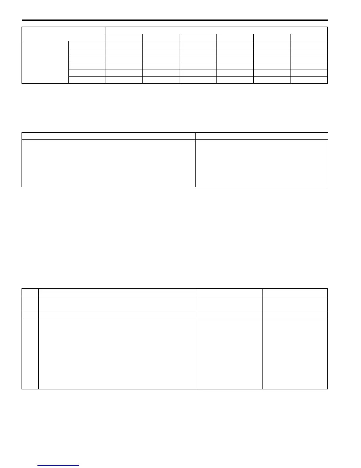
Terminal
E93-20 E93-1 E93-8 E93-7 E93-19 E93-18
Select lever
position
P 8 – 14 V 0 V 0 V 0 V 0 V 0 V
R 0 V8 – 14 V0 V0 V0 V0 V
N 0 V 0 V 8 – 14 V 0 V 0 V 0 V
D or 3 0 V 0 V 0 V 8 – 14 V 0 V 0 V
2 0 V0 V0 V0 V8 – 14 V0 V
L 0 V0 V0 V0 V0 V8 – 14 V
DTC Detecting Condition Trouble Area
Transmission range switch signal (P, R, N, D, 2, L) is not inputted
for more than 2 seconds in the following condition.
• Vehicle speed is more than 30 km/h (19 mile/h).
And
• Engine speed is more than 1500 rpm.
(2 driving cycle detection logic)
• Select cable maladjusted.
• Transmission range sensor (switch)
maladjusted.
• Transmission range sensor (switch) or its circuit
malfunction.
•TCM
Step Action Yes No
1 Was “A/T System Check” performed? Go to Step 2. Go to “A/T System
Check: ”.
2 Do you have SUZUKI scan tool? Go to Step 3. Go to Step 4.
3 Check transmission range sensor (switch) circuit for
operation
Check by using SUZUKI scan tool:
1) Connect SUZUKI scan tool to DLC with ignition switch
OFF.
2) Turn ignition switch ON and check transmission range
sensor signal (“P”, “R”, “N”, “D”, “2” or “L”) on display
when shifting select lever to each range.
Is applicable range indicated?
Intermittent trouble.
Check for intermittent
trouble referring to
“Intermittent and Poor
Connection Inspection:
in Section 00”.
Go to Step 5.

 Loading...


