Automatic Transmission/Transaxle: 5A-49
4 Check transmission range sensor (switch) circuit for
operation
Check without using SUZUKI scan tool:
1) Turn ignition switch ON.
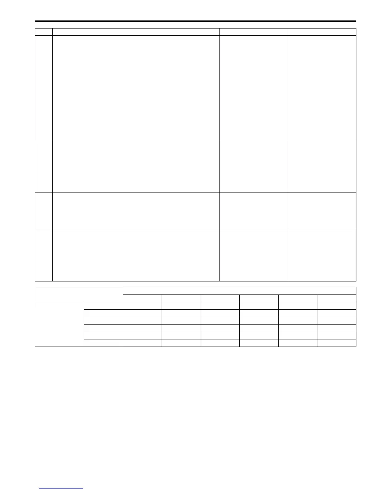
2) Check voltage at terminals “E93-1”, “E93-7”, “E93-8”,
“E93-18”, “E93-19” and “E93-20” respectively with select
lever shifted to each range.
Taking terminal “E93-1” as an example, is battery
voltage will be indicated only when shift lever is shifted to
“R” range and 0 V for other ranges as shown in table.
Check voltage at other terminals likewise, referring to
table.
Are check results satisfactory?
Intermittent trouble.
Check for intermittent
trouble referring to
“Intermittent and Poor
Connection Inspection:
in Section 00”.
Go to Step 5.
5 Check transmission range sensor (switch) for
installation position
1) Check transmission range sensor (switch) for installation
position referring to “Transmission Range Sensor
Inspection and Adjustment: ”.
Is it adjusted correctly?
Go to Step 6. Adjust transmission
range sensor (switch)
and recheck.
6 Check select cable for adjustment
1) Check select cable for adjustment referring to “Select
Cable Adjustment: ”.
Is it adjusted correctly?
Go to Step 7. Adjust select cable and
recheck.
7 Check transmission range sensor (switch)
1) Check transmission range sensor (switch) referring to
“Transmission Range Sensor Inspection and
Adjustment: ”.
Are check results satisfactory?
Transmission range
sensor circuit open or
shorted to ground. If
wires and connections
are OK, substitute a
known-good TCM and
recheck.
Replace transmission
range sensor (switch).
Step Action Yes No
Terminal
E93-20 E93-1 E93-8 E93-7 E93-19 E93-18
Select lever
position
P 8 – 14 V 0 V 0 V 0 V 0 V 0 V
R 0 V8 – 14 V0 V0 V0 V0 V
N 0 V 0 V 8 – 14 V 0 V 0 V 0 V
D or 3 0 V 0 V 0 V 8 – 14 V 0 V 0 V
2 0 V0 V0 V0 V8 – 14 V0 V
L 0 V0 V0 V0 V0 V8 – 14 V

 Loading...


