Air Bag System: 8B-85
NOTE
Upon completion of inspection and repair work, perform the following items.
• Reconnect all air bag system components, ensure all components are properly mounted.
• Clear DTCs referring to “DTC Clearance: ”, if any.
• Repeat “Air Bag Diagnostic System Check: ” to confirm that the trouble has been corrected.
DTC B1331 / B1335: Left / Right Side Curtain-Air Bag Initiator Circuit Resistance High
S5JB0A8204043
Wiring Diagram
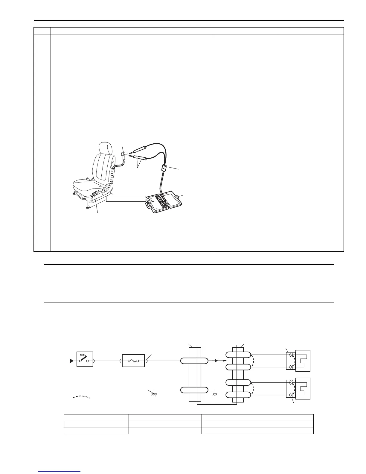
3 1) With ignition switch OFF, disconnect special tools (B)
and (C) then reconnect connector “L25” or “L30”.
2) Disconnect side-air bag (inflator) module connector
“Q02” or “Q03” from side-air bag (inflator) module.
3) Check proper connection to side-air bag (inflator)
module at terminal in connector.
4) If OK, then connect special tools (A), (B) and (C) to side-
air bag (inflator) connector.
Special tool
(A): 09932–76010
(B): 09932–75010
(D): 09932–78310
5) Check SDM DTC.
With ignition switch ON, is DTC B1064 or B1068 still
indicated?
DTC B1324: Repair
short from “GRY/RED”
or “GRY” wire circuit to
power circuit in seat
harness.
DTC B1328: Repair
short from “BRN/WHT”
or “BRN” wire circuit to
power circuit in seat
harness.
Replace side-air bag
(inflator) module
referring to“Side-Air Bag
(Inflator) Module
Removal and
Installation: ”.
Step Action Yes No
“L25”, “L30”
STEERING WHEEL
(B)
(D)
(A)
“Q02”, “Q03”
I5JB0A820046-02
[A]
BLK
G46-16 GND
“G46”
1
2
4
3
RED
BLK/YEL
“G01”
G46-11 IG
“L32”
YEL/GRN
YEL/BLU
BLK/YEL
BRN/YEL
“G18”
“G41”
L32-1
L32-2
L32-4
L32-3RC-
RC+
LC-
LC+
8
5
6
7
I5JB0A820056-01
[A]: Shorting bar 3. “A/B” fuse 6. Left side curtain-air bag (inflator) module
1. From main fuse 4. Junction block assembly 7. Right side curtain-air bag (inflator) module
2. Ignition switch 5. SDM 8. Ground for air bag system