ABS: 4E-27
DTC U1073: Control Module Communication Bus Off
S5JB0A4504020
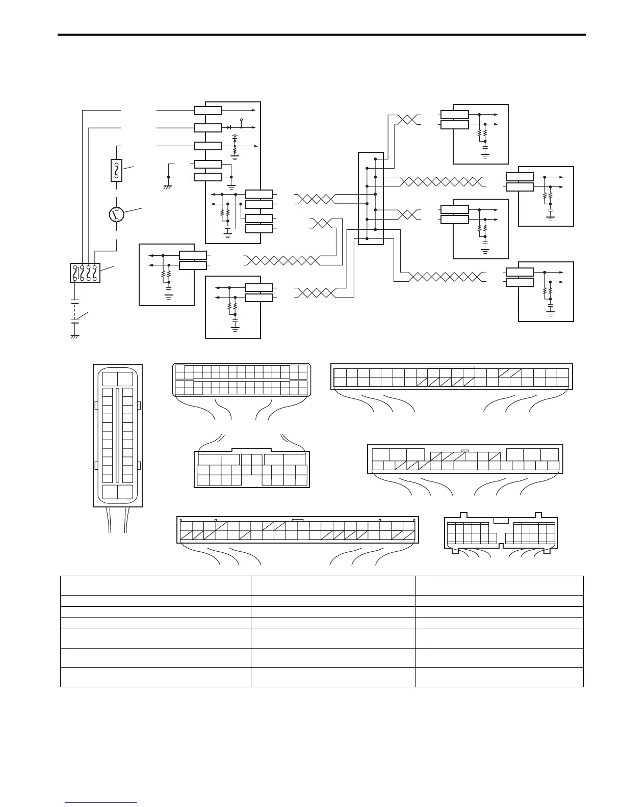
Wiring Diagram
DTC Detecting Condition
Transmission error that is inconsistent between transmission data and transmission monitor (CAN bus monitor) data is
detected more than 7 times continuously.
WHT
RED
WHT
RED
WHT/BLU
WHT/RED
WHT
RED
WHT
RED
E92-17
E92-7
E03-12
E03-6
E03-10
E03-8
12V
12V
E03-1
E03-14
E03-7
E03-13
E03-26
GRN/ORN
BLK/YEL
WHT/GRN
WHT/RED
WHT/BLU
[A]
[D]
WHT/BLU
WHT/RED
E23-19
E23-4
E91-22
E91-23
WHT
RED
WHT
RED
BLK
BLK
E03
G31-1
G31-3
[B] [C]
[G][F]
G44
1234567891011141516
36 34 33 32 31 30 29 24 2337
181920
65
16 15 14 13 12 11
43
24 23 2122
10 9 8 7
21
1920 18 17
E92
21
E23
34
1819
5671011
17
20
47 46
495051
2122
52
16
25
9
24
14
29
5557 5453
59
60
58
26
27
28
15
30
56
48
32 31343536374042 3938
44
45 43 41 33
1213
23
8
12345678910
1117 16151413122221201918
G28
G31
12347891011141516
36 3435 24 23 212228 27 25263739 3840
18 17 13 121920
E91
123101112
161718 15 14 131920212526
56
[E]
G44-18
G44-19
G28-10
G28-8
6
7
1
2
3
4
5
12
8
9
10
11
15
16
17
18
19
20
21
22
23
24
25
2
3
4
5
6
7
8
9
10
11
12
1
13
14
26
I5JB0A450020-02
[A]: ABS hydraulic unit / control module connector
(viewed from terminal side)
1. Battery 8. TCM (for A/T model)
[B]: ECM connector (viewed from harness side) 2. Main fuse box 9. 4WD control module (if equipped)
[C]: BCM connector (viewed from harness side) 3. Ignition switch 10. Keyless start control module (if equipped)
[D]: TCM connector (viewed from harness side) 4. Circuit fuse (in junction block assembly) 11. Combination meter
[E]: 4WD control module connector
(viewed from harness side)
5. ABS hydraulic unit / control module
assembly
12. CAN junction
[F]: Keyless start control module connector
(viewed from harness side)
6. ECM
[G]: Combination meter connector (viewed from
harness side)
7. BCM

 Loading...


