10B-6 Body Electrical Control System:
Diagnostic Information and Procedures
BCM Self-Diagnosis Function
S5JB0AA204001
• BCM monitors conditions of the system components and its circuit with ignition switch turned to ON position. When
an abnormality in the system occurs, the area where that abnormality lies is stored in the memory of EEPROM in
BCM.
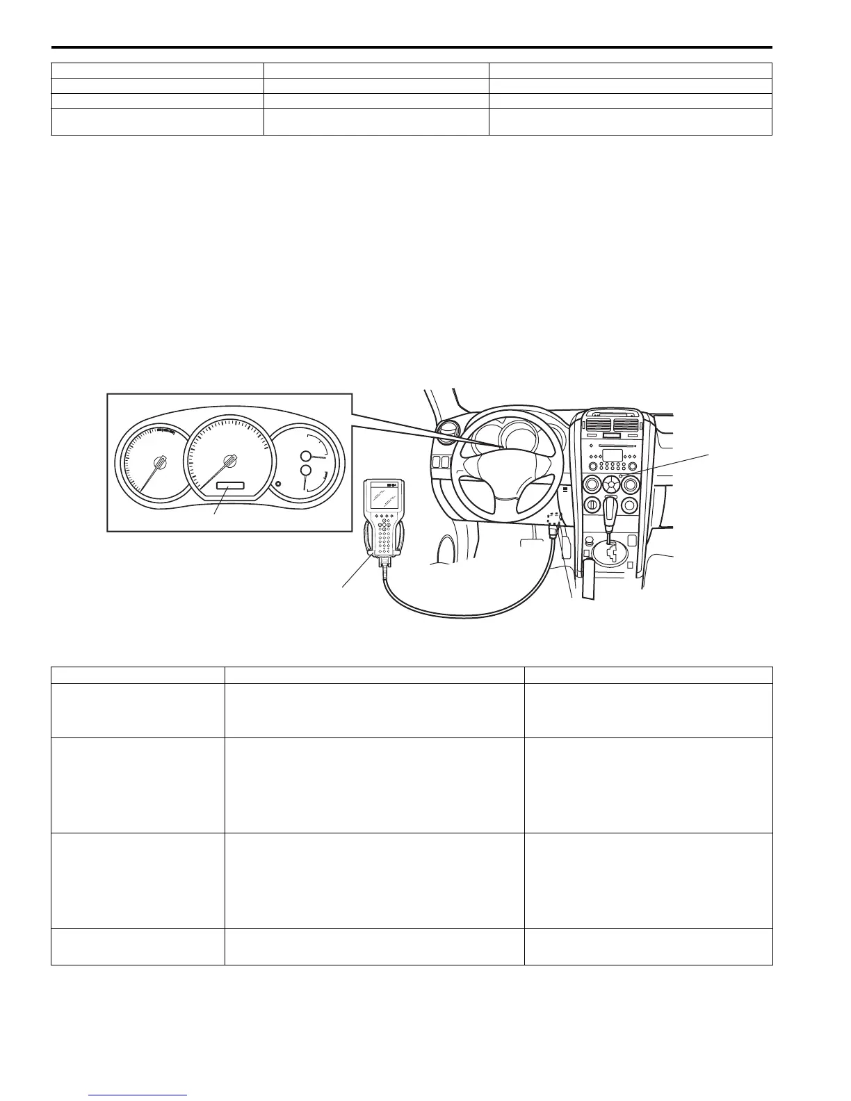
• DTC can be checked in either one of following ways.
– DTC can be checked by SUZUKI scan tool (2) connected to DLC (1).
– DTC can be read from flashing pattern of alarm indicator lamp (3). In addition, when alarm indicator is flashing for
DTC outputting DTC is displayed on combinations meter (4) at the same time.
BCM input / output table
7. Door switch 17. Hazard warning switch 27. Front fog light switch
8. Interior light 18. Rear wiper switch 28. Turn signal and hazard warning relay
9. Luggage room light 19. Lighting switch 29. Key reminder switch (included in ignition switch)
10. Rear end door lock actuator
(incorporated in door switch)
20. Manual door lock switch
3
1
2
4
I5JB0AA20004-01
Control Input Output
Power door lock system
• Key cylinder switch
• Manual door lock switch
• Driver side door lock actuator
• Other than driver side door lock
actuator
Keyless entry system
• Key reminder switch
• Keyless entry receiver
• Driver side door switch
• Driver side door lock actuator
• Other than driver side door lock
actuator
• Turn signal and hazard warning relay
• Interior light
Keyless start system
(Door lock function)
• Keyless start control module • Driver side door lock actuator
• Other than driver side door lock
actuator
• Turn signal and hazard warning relay
• Interior light
Rear wiper
• Rear wiper INT switch
• Rear wiper LO switch
• Rear wiper relay

 Loading...


