5A-68 Automatic Transmission/Transaxle:
DTC P1874 4L Switch Circuit Malfunction (Short)
S5JB0A5104047
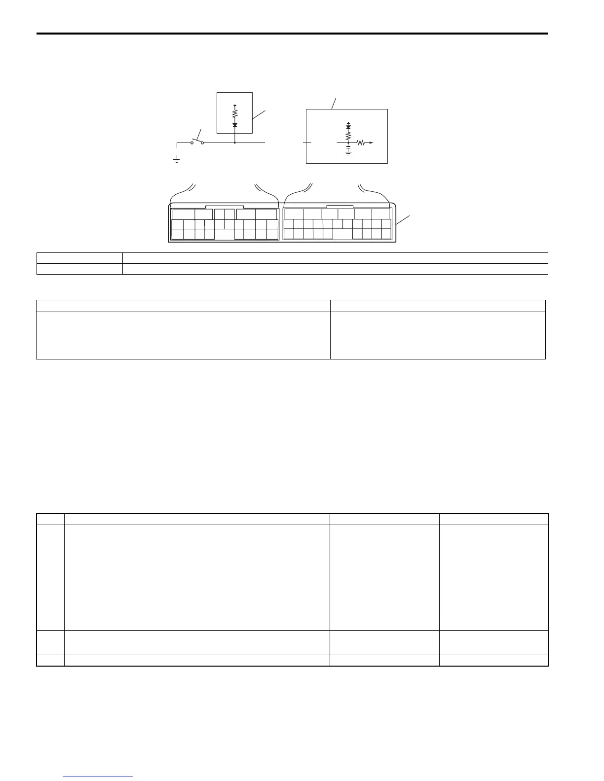
Wiring Diagram
DTC Detecting Condition and Trouble Area
DTC Confirmation Procedure
1) Connect scan tool to DLC with ignition switch OFF.
2) Clear DTCs in TCM and ECM memories by using scan tool.
3) Start engine and transfer position switch to “4H” position.
4) Keep engine running at idle speed for 10 seconds or more with select lever “D” range.
5) Start vehicle and increase vehicle speed to about 60 km/h (37 mile/h) for 2 minutes.
6) Stop vehicle.
7) Check DTC, pending DTC and freeze frame data.
DTC Troubleshooting
12V
12V
PNK/WHT
BLK
E93-4
1
2
4
3
65
16 15 14 13 12 11
43
24 23 2122
10 9 8 7
21
1920 18 17
E92
17 16
26 25
15 14
65 342
13 12
23 2224
11 10 9
21 20 19
87
18
1
E93
I5JB0A510026-01
1. 4L/N switch 3. 4WD control module
2. TCM 4. Terminal arrangement of TCM connector (viewed from harness side)
DTC Detecting Condition Trouble Area
Actual transfer position is 4H although TCM detected 4L/N switch
is turned ON with vehicle speed between 29 km/h (18 mile/h) and
88 km/h (55 mile/h).
(1 driving cycle detection logic)
• 4L/N switch or its circuit.
•TCM
Step Action Yes No
1 Vehicle speed signal check
1) Check DTC in ECM and ABS hydraulic unit / control
module referring to “DTC Check: in Section 1A” or “DTC
Check: in Section 4E”.
Is there DTC P P0500: Vehicle speed sensor (VSS)
malfunction in ECM and/or DTC C1021, C1022, C1025,
C1026, C1031, C1032, C1035 and/or C1036 in ABS
hydraulic unit / control module?
Go to applicable DTC
diag. flow.
Go to Step 2.
2 Was “A/T System Check” performed? Go to Step 2. Go to “A/T System
Check: ”.
3 Do you have SUZUKI scan tool? Go to Step 4. Go to Step 5.

 Loading...


