Air Conditioning System: 7B-56
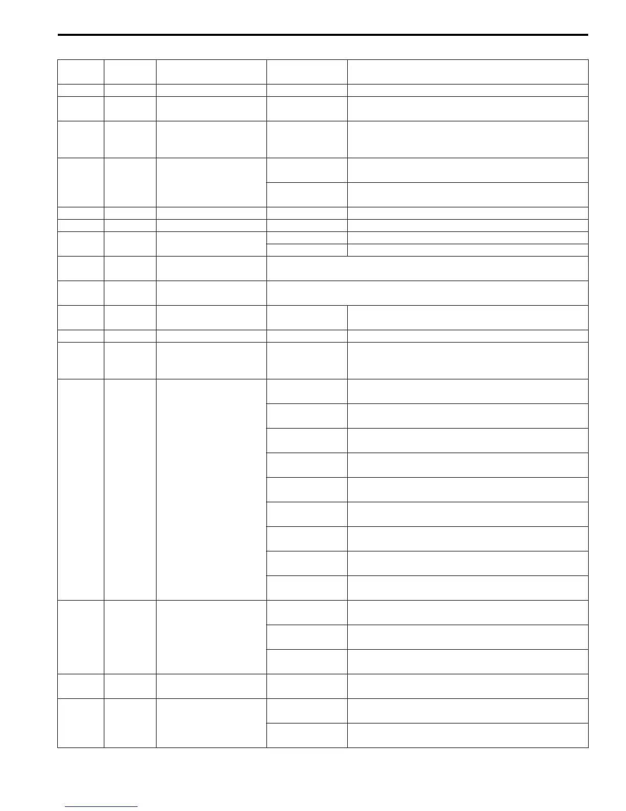
HVAC Control Module Voltage Table
Terminal
Wire
color
Circuit Normal value Condition
G52-1 PPL/RED Power supply 10 – 14 V Ignition switch turned ON.
G52-2 WHT
Electric power source
for back-up
10 – 14 V Constantly.
G52-3 PPL/WHT
Serial communication
line of data link
connector
10 – 14 V Ignition switch turned ON.
G52-4 RED/YEL Illumination switch
0 – 1 V
Ignition switch turned ON, lighting switch OFF
position.
10 – 14 V
Ignition switch turned ON, lighting switch ON
position.
G52-5 RED/GRN Illumination ground 0 – 1 V Constantly.
G52-6 PNK/BLK Alarm indicator — —
G52-8 BLK/RED
Rear defogger driving
signal
10 – 14 V Ignition switch turned ON, rear defogger switch ON.
0 – 1 V Ignition switch turned ON, rear defogger switch OFF.
G52-10 YEL/RED
Serial communication
line from BCM
Refer to “Inspection of BCM and its Circuits: in Section 10B”.
G52-11 PNK/GRN
Serial communication
line to BCM
Refer to “Reference waveform No. 1: ”.
G52-12 YEL
Ground for sunload
sensor
0 – 1 V Constantly.
G52-13 BLK/RED Ground for sensors 0 – 1 V Constantly.
G52-14 RED/WHT
Output of 5 V power
source for position
sensor of actuators
4 – 6 V Ignition switch turned ON.
G52-15 RED/BLK
Blower motor control
voltage feedback
Approx. 12 V
Ignition switch turned ON, blower speed selector
OFF.
Approx. 8 V
Ignition switch turned ON, blower speed selector 1st
position.
Approx. 7 V
Ignition switch turned ON, blower speed selector 2nd
position.
Approx. 5.5 V
Ignition switch turned ON, blower speed selector 3rd
position.
Approx. 4.5 V
Ignition switch turned ON, blower speed selector 4th
position.
Approx. 3 V
Ignition switch turned ON, blower speed selector 5th
position.
Approx. 1.3 V
Ignition switch turned ON, blower speed selector 6th
position.
Approx. 0.3 V
Ignition switch turned ON, blower speed selector 7th
position.
Less than 0.3 V
Ignition switch turned ON, blower speed selector 8th
position.
G52-16 PPL/GRN Blower motor controller
0 – 1 V
Ignition switch turned ON, blower speed selector
OFF.
Approx. 4.2 V
Ignition switch turned ON, blower speed selector 1st
– 7th position.
Approx. 5.7 V
Ignition switch turned ON, blower speed selector 8th
position.
G52-17 BLK
Ground for HVAC
control module
0 – 1 V Constantly.
G52-18 PNK Sunload sensor signal
Approx. 3 V
Ignition switch turned ON, amount of insolation is
500 W/m
2
Approx. 5 V
Ignition switch turned ON, amount of insolation is 0
W/m
2

 Loading...


