Engine General Information and Diagnosis: 1A-196
DTC Troubleshooting
NOTE
Before this trouble shooting is performed, read the precautions for DTC troubleshooting referring to
“Precautions For DTC Troubleshooting: ”.
Step Action Yes No
1 Was “Engine and Emission Control System Check”
performed?
Go to Step 2. Go to “Engine and
Emission Control
System Check: ”
2 Accelerator pedal position (APP) sensor assembly
mounting check
1) Check that accelerator pedal position (APP) sensor
assembly has been mounted to vehicle body properly
(no pinched floor carpet, etc).
Is it OK?
Go to Step 3. Reinstall accelerator
pedal position (APP)
sensor assembly
properly referring to
“Accelerator Pedal
Position (APP) Sensor
Assembly Removal and
Installation: in Section
1C”.
3 Accelerator pedal position sensor (main) and its circuit
check
1) Connect scan tool to DLC with ignition switch turned
OFF.
2) Turn ON ignition switch, check “APP Sensor 1 Volt”
displayed on scan tool.
Is displayed voltage below 0.1 V?
Go to Step 4. Intermittent trouble.
Check for intermittent
referring to “Intermittent
and Poor Connection
Inspection: in Section
00”.
4 ECM voltage check
1) Disconnect connector from accelerator pedal position
(APP) sensor assembly with ignition switch turned OFF.
2) Check for proper connection to accelerator pedal
position (APP) sensor assembly at “WHT”, “WHT/BLU”
and “ORN” wire terminals.
3) If OK, measure voltage between “WHT” wire terminal of
accelerator pedal position (APP) sensor assembly
connector and vehicle body ground with ignition switch
turned ON.
Is voltage 4 – 6 V?
Go to Step 7. Go to Step 5.
5 ECM voltage check
1) Turn OFF ignition switch.
2) Remove ECM from its bracket with ECM connectors
connected.
3) Check for proper connection of ECM connector at “E23-
56” terminal.
4) If OK, measure voltage between “E23-56” terminal of
ECM connector and engine ground with ignition switch
turned ON.
Is voltage 4 – 6 V?
“WHT” wire is open or
high resistance circuit.
Go to Step 6.
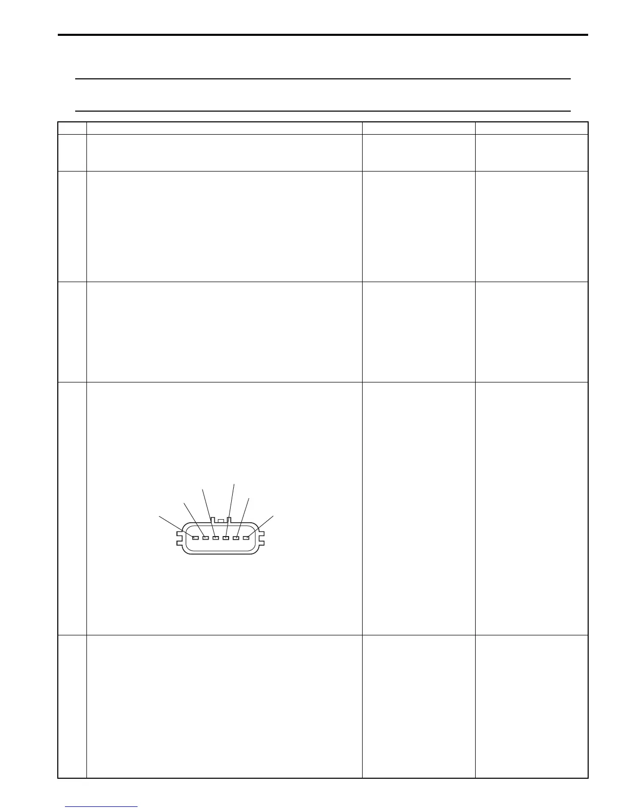
“BLU/GRN”
“BLU/YEL”
“ORN”
“WHT/BLU”
“WHT”
“ORN BLU”
I5JB0A110071-01

 Loading...


