1A-213 Engine General Information and Diagnosis:
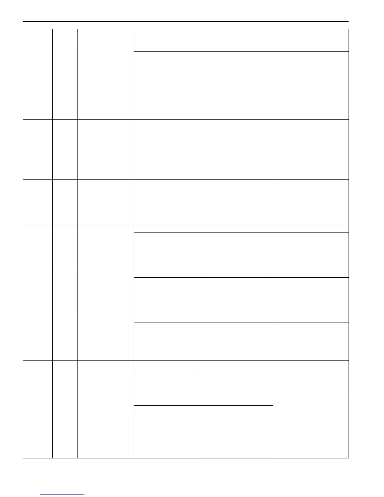
Terminal
No.
Wire
color
Circuit Normal voltage Condition Remarks
C37-1 PNK Fuel injector No.1
10 – 14 V Ignition switch turned ON. —
*0 – 0.6 V
↑↓
10 – 14 V
(“Reference
waveform No.1: ”,
“Reference waveform
No.2: ” and
“Reference waveform
No.31: ”)
Engine running at idle
after warmed up engine.
Output signal is active low
pulse. Pulse frequency
varies depending on
engine speed.
C37-2
PNK/
BLK
Fuel injector No.2
10 – 14 V Ignition switch turned ON. —
*0 – 0.6 V
↑↓
10 – 14 V
(“Reference
waveform No.1: ” and
“Reference waveform
No.3: ”)
Engine running at idle
after warmed up engine.
Output signal is active low
pulse. Pulse frequency
varies depending on
engine speed.
C37-3
YEL/
GRN
EGR valve
(stepper motor coil
3)
10 – 14 V Ignition switch turned ON. —
*0 – 1 V
↑↓
10 – 14 V
(“Reference
waveform No.4: ”)
Ignition switch is turned to
ST (cranking) position.
Output signal is active low
duty pulse. Number of
pulse generated times
varies depending on
vehicle condition.
C37-4 YEL
EGR valve
(stepper motor coil
4)
10 – 14 V Ignition switch turned ON. —
*0 – 1 V
↑↓
10 – 14 V
(“Reference
waveform No.4: ”)
Ignition switch is turned to
ST (cranking) position.
Output signal is active low
duty pulse. Number of
pulse generated times
varies depending on
vehicle condition.
C37-5
YEL/
BLK
EGR valve
(stepper motor coil
1)
10 – 14 V Ignition switch turned ON. —
*0 – 1 V
↑↓
10 – 14 V
(“Reference
waveform No.4: ”)
Ignition switch is turned to
ST (cranking) position.
Output signal is active low
duty pulse. Number of
pulse generated times
varies depending on
vehicle condition.
C37-6
YEL/
RED
EGR valve
(stepper motor coil
2)
10 – 14 V Ignition switch turned ON. —
*0 – 1 V
↑↓
10 – 14 V
(“Reference
waveform No.4: ”)
Ignition switch is turned to
ST (cranking) position.
Output signal is active low
duty pulse. Number of
pulse generated times
varies depending on
vehicle condition.
C37-7
BLU/
ORN
Power steering
pump pressure
switch signal
10 – 14 V Ignition switch turned ON.
—
0 – 1 V
With engine at idle speed,
turning steering wheel to
the right or left as far as it
stops.
C37-8
BRN/
RED
(for M16
engine)
BRN/
BLK (for
J20
engine)
Generator field coil
monitor signal
10 – 14 V Ignition switch turned ON.
Signal is duty pulse. Duty
ratio varies depending on
vehicle condition.
*0 – 1 V
↑↓
10 – 14 V
(“Reference
waveform No.5: ” and
“Reference waveform
No.6: ”)
Engine running at idle
after warmed up engine.

 Loading...


