Engine Mechanical: 1D-43
3) Remove the front output shaft (4) and rear output
shaft (5). (LT-F400F)
4) Remove the rear output shaft (5). (LT-F400)
Balancer
1) Remove the balancershaft driven gear (1).
2) Remove the Key (2).
3) Remove the balancershaft with the special tools.
Special tool
(A): 09930–30104 (Rotor remover slide
shaft)
(B): 09930–30141 (Attachment A)
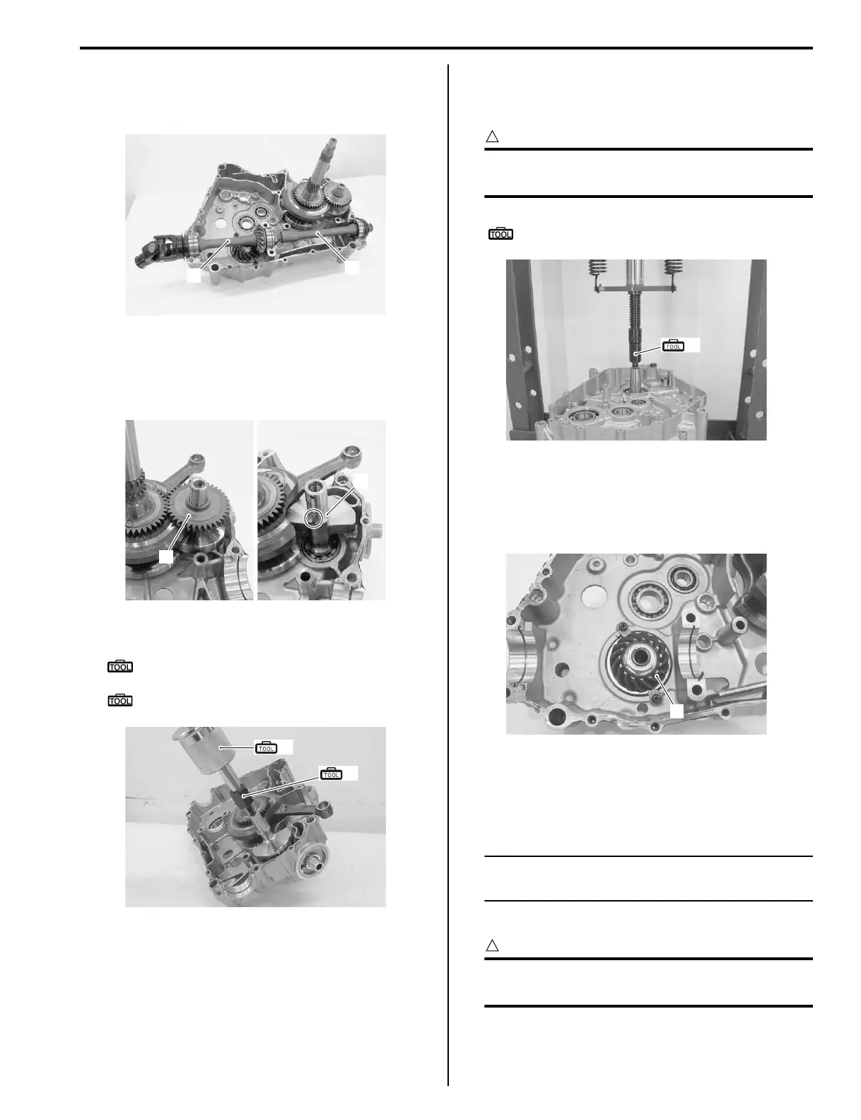
Camshaft
1) Remove the crankshaft using the special tool and a
hydraulic press.
CAUTION
!
Be sure to hold the crankshaft when pressing
it out of the crankcase.
Special tool
(A): 09930–31921 (Rotor remover)
Drive Bevel Gear and Output Shaft
Remove the drive bevel gear (1) and output shaft. Refer
to “Drive Bevel Gear Removal and Installation (LT-F400/
F) in Section 3D (Page 3D-15)”.
Engine Bottom Side Assembly
B827H11406034
Assemble the engine bottom side in the reverse order of
disassembly. Pay attention to the following points:
NOTE
Apply engine oil to each running and sliding
part before reassembling.
LT-A400/F
CAUTION
!
Always keep the drive belt, drive face and
driven face away from any greasy matter.
Output Shaft and Drive Bevel Gear
• Install the output shaft and Drive Bevel Gear. Refer to
“Transfer Removal and Installation (LT-F400/F) in
Section 3C (Page 3C-7)”.
5
4
I827H1140150-01
1
2
I827H1140151-01
(A)
(B)
I827H1140258-01
(A)
I827H1140259-03
1
I827H1140260-01
 Loading...


