3D-10 Propeller Shafts:
• After reassembling the universal joint, check the joint
movement smoothly. If a large resistance is felt to
movement, tap the bearing with a plastic mallet lightly.
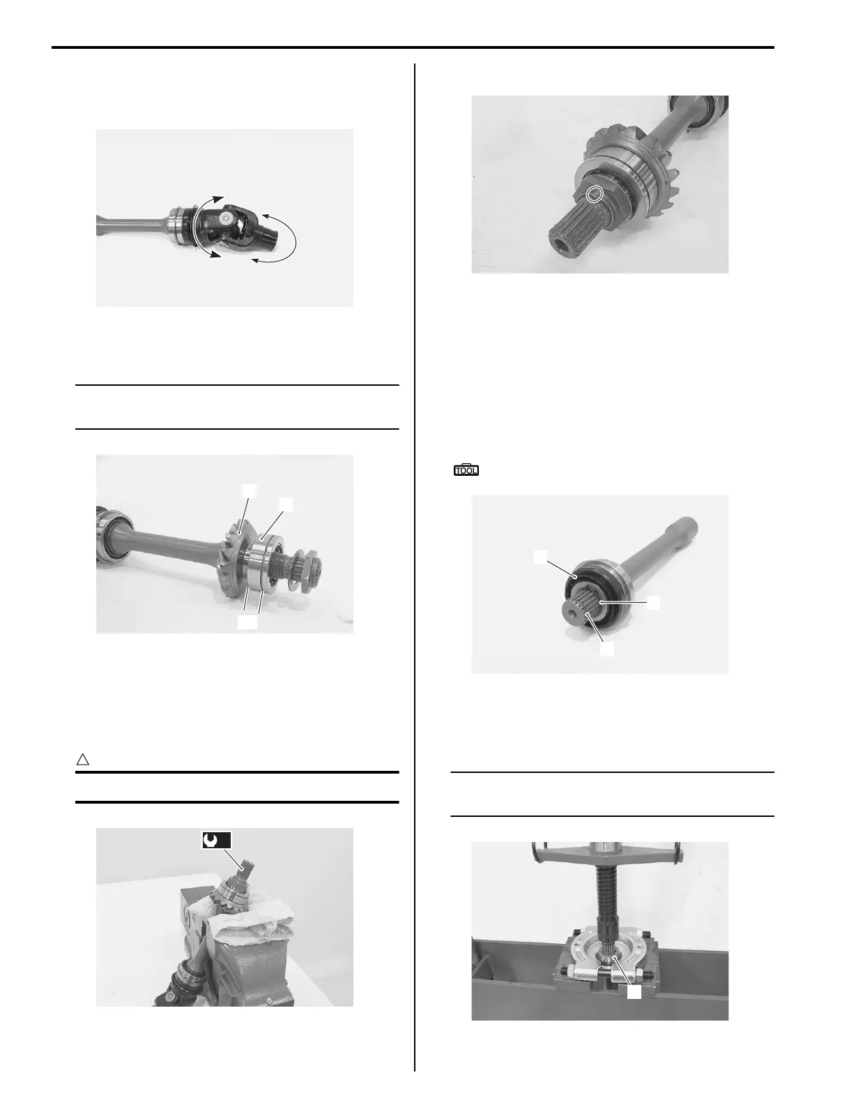
• Install the driven bevel gear (4), bearing (5), washer
and nut.
NOTE
The wider side “C” of the bearing should be
positioned driven bevel gear side.
• With the rear output shaft held immovable with a vise,
tighten new nut to the specified torque.
Tightening torque
Driven bevel gear nut (a): 100 N·m (10.0 kgf-m,
72.5 lb-ft)
CAUTION
!
Replace the removed nut with a new one.
• Stake the nut with a center punch.
Front Output Shaft Disassembly and Assembly
(LT-A400F, LT-F400F)
B827H13406018
Refer to “Output Shaft Removal and Installation
(Page 3D-3)”.
Disassembly
1) Remove the oil seal (1), circlip (2) and snap ring (3).
Special tool
: 09900–06107 (Snap ring pliers)
2) Remove the spacer (4) using a commercially
available bearing puller and hydraulic press.
3) Remove the bearing.
NOTE
If there is no abnormal noise, the spacer and
bearing removal is not necessary.
I827H1340050-02
“C”
5
4
I827H1340051-03
(a)
I827H1340052-01
I827H1340053-01
1
3
2
I827H1340054-02
4
I827H1340087-01
 Loading...


