1I-7 Starting System:
3) Remove the neutral relay (1).
Installation
Install the neutral relay in the reverse order of removal.
Neutral Relay Inspection
B827H11906008
Inspect the neutral relay in the following procedures:
1) Remove the neutral relay. Refer to “Neutral Relay
Removal and Installation (Page 1I-6)”.
2) Check the insulation between “A” and “B” terminals
using the multi-circuit tester.
3) Apply 12 V to terminals “C” and “D” ((+) to “C” and (–
) to “D”) and check the continuity between “A” and
“B”. If there is no continuity, replace the neutral relay
with a new one.
Special tool
: 09900–25008 (Multi-circuit tester set)
Tester knob indication
Continuity test ( )
4) Install the neutral relay. Refer to “Neutral Relay
Removal and Installation (Page 1I-6)”.
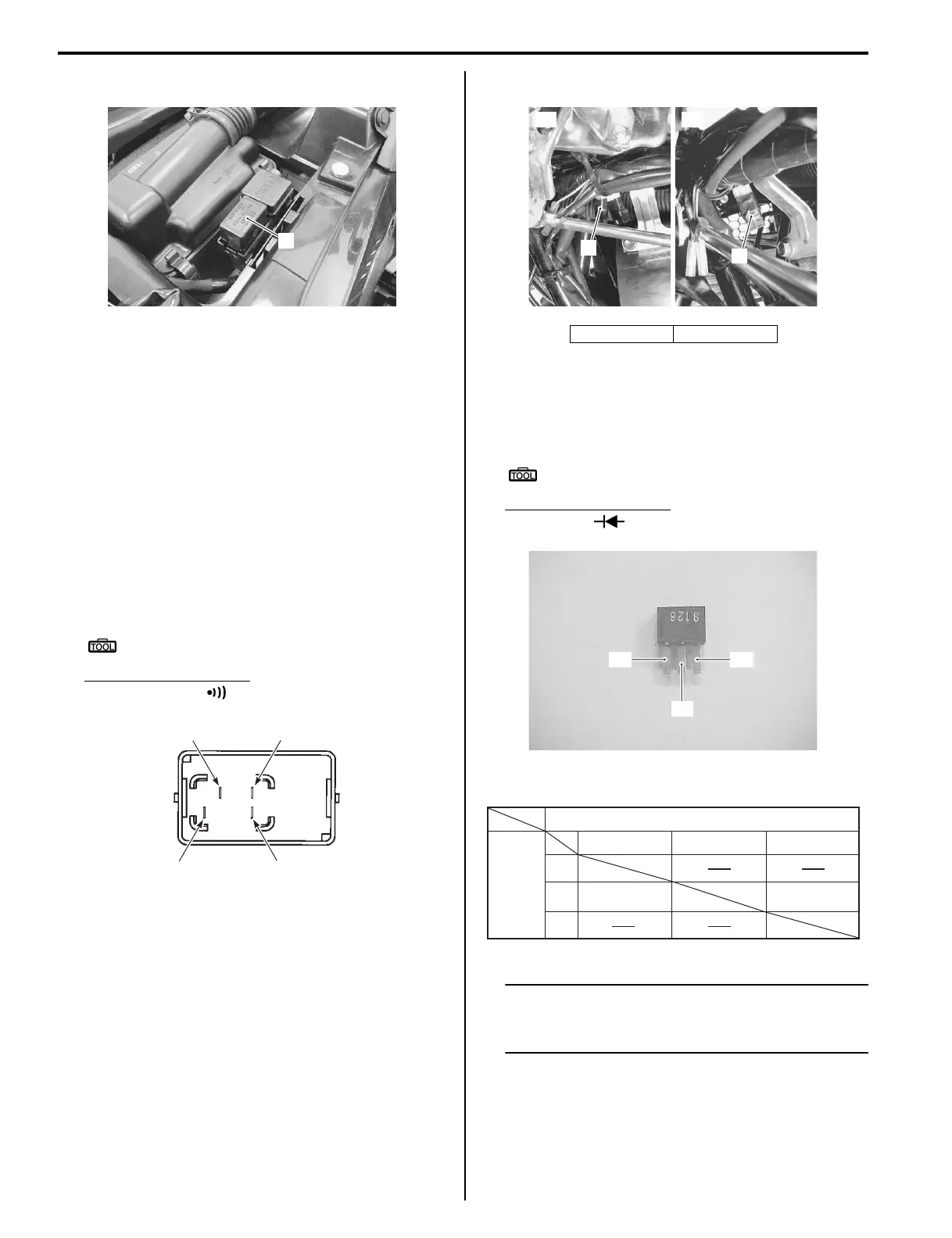
Neutral Switch Diode Inspection
B827H11906009
Refer to “Electrical Components Location in Section 0A
(Page 0A-6)”.
Inspect the neutral switch diode in the following
procedures:
1) Remove the left inner fender. Refer to “Exterior Parts
Removal and Installation in Section 9D (Page 9D-
3)”.
2) Disconnect the neutral switch diode (1).
3) Measure the voltage between the “A” and “B”
terminals using the multi-circuit tester. If any
abnormality is found, replace the diode with a new
one.
Special tool
: 09900–25008 (Multi-circuit tester set)
Tester knob indication
Diode test ( )
NOTE
If the multi circuit tester reads 1.4 V and
below when the tester probes are not
connected, replace its battery.
1
I827H1190012-01
“C”
“D”
“A”
“B”
I831G1190016-02
[A] LT-A400/F [B] LT-F400/F
1
[A] [B]
1
I827H1190013-02
“C”
“A”
“B”
I827H1190014-01
(+)Tester probe
“B”
“C”
“A” “C”“B”
“A”
–0.4 0.6
(–) tester
Probe
–0.4 0.6
Unit: V
I827H1190015-02
 Loading...


