5B-9 Manual Transmission:
Installation
Install the gearshift lever assembly in the reverse order
of removal. Pay attention to the following points:
• Apply grease to the O-rings and pedal pivot.
CAUTION
!
Replace the O-rings with new ones.
: Grease 99000–25010 (SUZUKI SUPER
GREASE A or equivalent)
• Install the snap ring (1).
CAUTION
!
Never reuse the removed snap ring.
• Install the left footrest to the frame. Refer to “Footrest
Removal and Installation in Section 9E (Page 9E-2)”.
• Install the gearshift link arm in the following angle.
• Check the gearshift lever height. Refer to “Gearshift
Lever Height Inspection and Adjustment (LT-F400/F)
(Page 5B-9)”.
Gearshift Lever Height Inspection and
Adjustment (LT-F400/F)
B827H15206014
Inspect and adjust the gearshift lever height in the
following procedures:
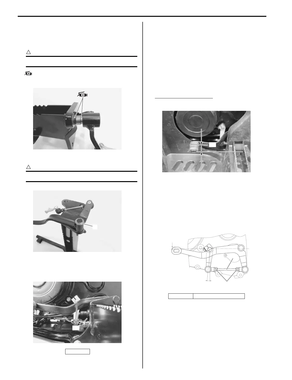
1) Inspect the gearshift lever height “a” between the
pedal top face and footrest.
Adjust the gearshift lever height if necessary.
Gearshift lever height “a”
Standard: 0 – 10 mm (0.0 – 0.4 in)
2) Remove the left footrest mudguard. Refer to
“Exterior Parts Removal and Installation in Section
9D (Page 9D-3)”.
3) Loosen the lock-nuts (1).
4) Turn the gearshift link rod (2) until the gearshift lever
is 0 – 10 mm (0.0 – 0.4 in) higher than the top of the
footrest.
5) Tighten the lock-nuts securely.
6) Reinstall the removed parts.
“a”: 5°
I827H1520035-01
1
I827H1520036-01
“a”
I827H1520037-02
“a”: 5° “b”: 0 – 10 mm (0.0 – 0.4 in)
“a”
I827H1520020-01
1
2
“a”
“b”
I827H1520021-03
 Loading...


