Brake Control System and Diagnosis: 4A-12
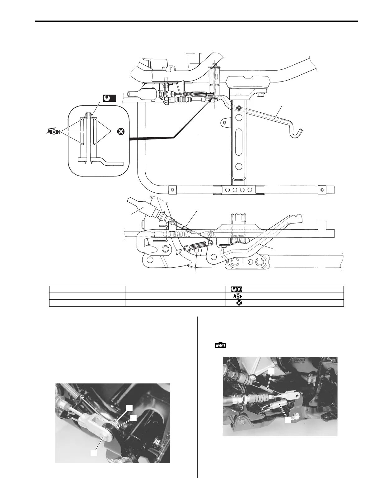
Rear Brake Pedal Construction
B827H14106017
Rear Brake Pedal Removal and Installation
B827H14106018
Removal
1) Remove the right footrest mudguard. Refer to
“Exterior Parts Removal and Installation in Section
9D (Page 9D-3)”.
2) Remove the cotter pin (1), washer (2) and pin (3).
3) Remove the brake light switch spring (4) and brake
pedal spring (5).
Special tool
: 09920–20310 (Clutch spring hook)
(a)
5
6
1
2
3
4
1
I827H1410037-03
1. Rear brake pedal 4. Brake light switch spring : 12 N⋅m (1.2 kgf-m, 8.5 lb-ft)
2. Rear brake light switch 5. Rear brake pedal pivot nut : Apply grease.
3. Brake pedal spring 6. O-ring : Do not reuse.
1
3
2
I827H1410031-01
4
5
I827H1410032-01
 Loading...


