3D-4 Propeller Shafts:
• Insert C-ring (1).
• Check that the output shaft(-s) rotates smoothly.
• Assemble the engine. Refer to “Engine Bottom Side
Assembly in Section 1D (Page 1D-43)” and “Engine
Top Side Assembly in Section 1D (Page 1D-13)”.
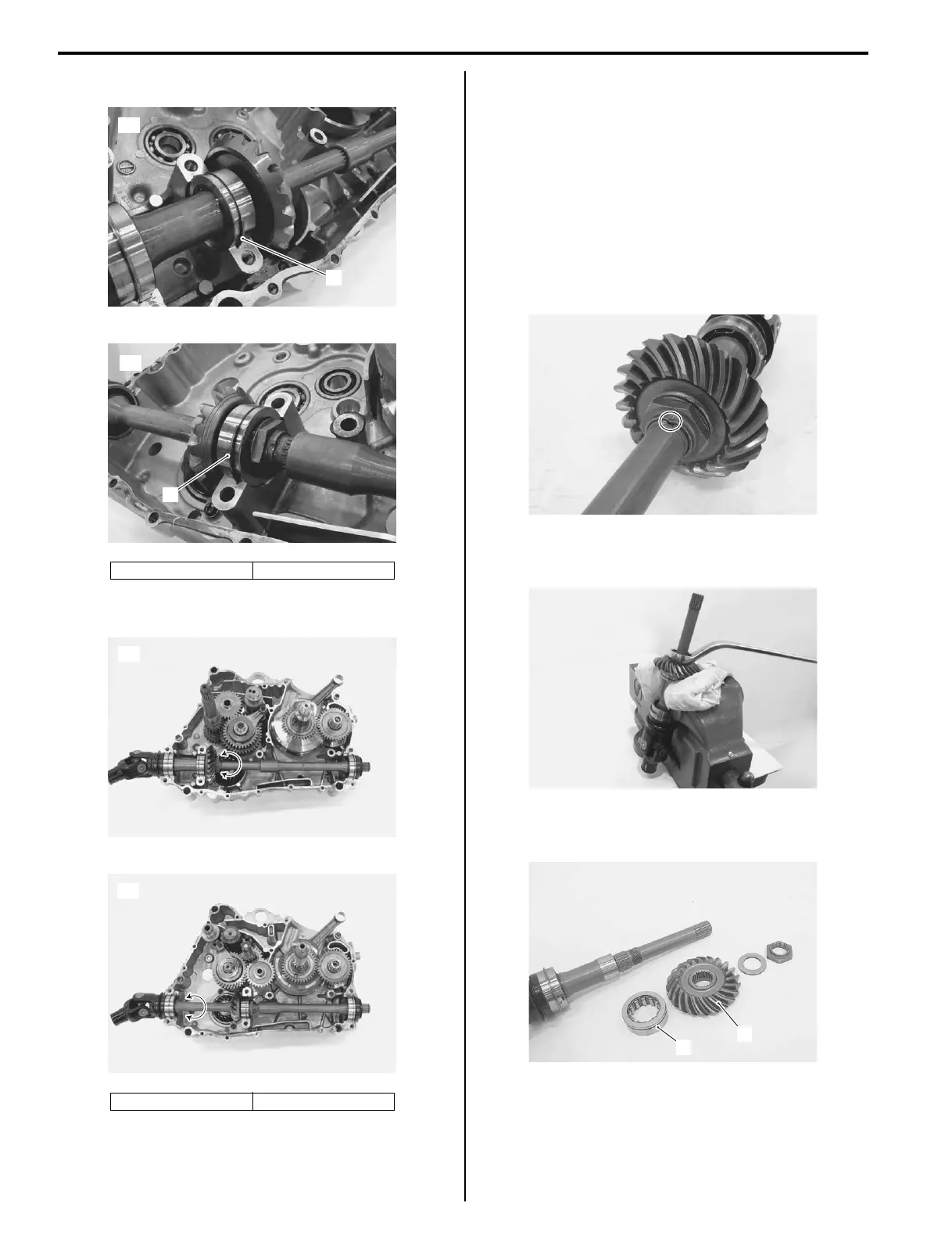
Rear Output Shaft Disassembly and Assembly
(LT-A400/F)
B827H13406016
Refer to “Output Shaft Removal and Installation
(Page 3D-3)”.
Disassembly
1) Using a chisel, unlock the nut.
2) With the rear output shaft held immovable with a
vise, remove the nut.
3) Remove the washer, driven bevel gear (1) and
bearing (2).
[A]: LT-A400F [B]: LT-F400F
[A]: LT-A400F [B]: LT-F400F
1
[A]
I827H1340013-02
1
[B]
I827H1340014-02
[A]
I827H1340015-01
[B]
I827H1340016-01
I827H1340017-01
I827H1340018-01
1
2
I827H1340019-01
 Loading...


