Engine Lubrication System: 1E-8
• Install the oil pump drive gear (3) so that its flange
side faces side faces the crankcase side.
• Apply thread lock to the oil pump drive gear bolt.
: Thread lock cement 99000–32030
(THREAD LOCK CEMENT SUPER 1303 or
equivalent)
• Tighten the oil pump drive gear bolt to the specified
torque using the special tool.
Special tool
(A): 09930–40113 (Rotor holder)
Tightening torque
Oil pump drive gear bolt (a): 80 N·m (8.0 kgf-m,
58.0 lb-ft)
• Install the drive V-belt covers. (LT-A400/F). Refer to
“Clutch Shoe Removal and Installation in Section 5A
(Page 5A-16)”.
• Install the clutch cover. (LT-F400/F). Refer to “Clutch
Removal and Installation (LT-F400/F) in Section 5C
(Page 5C-3)”.
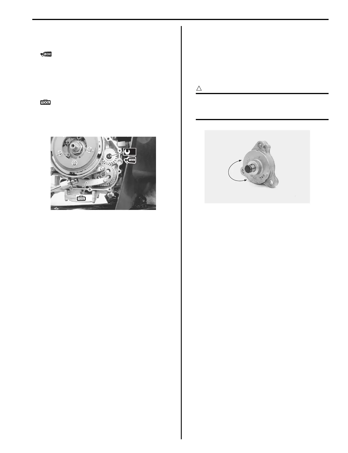
Oil Pump Inspection
B827H11506008
Inspect the oil pump in the following procedures:
1) Remove the oil pump. Refer to “Oil Pump Drive Gear
/ Oil Pump Removal and Installation (Page 1E-6)”.
2) Rotate the oil pump by hand and check that it moves
smoothly. If it does not move smoothly, replace the
oil pump with a new one.
CAUTION
!
Do not attempt to disassemble the oil pump.
The oil pump is available only as an
assembly.
3) Install the oil pump. Refer to “Oil Pump Drive Gear /
Oil Pump Removal and Installation (Page 1E-6)”.
(A)
(a)
I827H1150018-01
I827H1150019-01
 Loading...


