Transfer: 3C-4
Transfer Removal and Installation (LT-A400/F)
B827H13306002
Removal
1) Remove the engine assembly from the frame. Refer
to “Engine Assembly Removal in Section 1D
(Page 1D-6)”.
2) Remove the engine top side. Refer to “Engine Top
Side Disassembly in Section 1D (Page 1D-10)”.
3) Separate the crank case. Refer to “Engine Bottom
Side Disassembly in Section 1D (Page 1D-34)”.
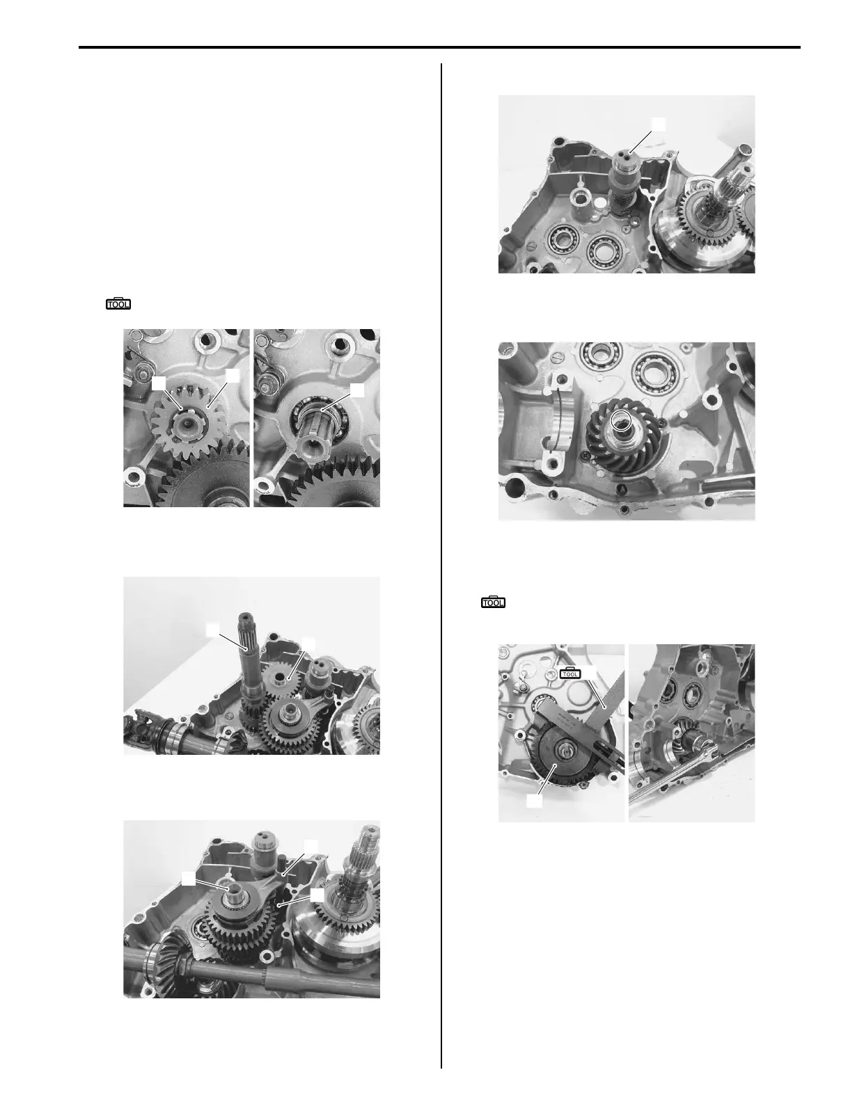
4) Remove the snap ring (1), drive gear No. 2 (2) and
spacer (3).
Special tool
: 09900–06107 (Snap ring pliers)
5) Remove the reverse idle gear (4).
6) Remove the transfer input shaft (5).
7) Remove the transfer countershaft assembly (6),
reverse gearshift fork (7) and gearshift fork (8).
8) Remove the transfer gearshift cam assembly (9).
9) Remove the output shaft.
10) Using a chisel, unlock the drive bevel gear nut.
11) Hold the transfer driven gear (10) with the special
tool and remove the drive bevel gear nut.
Special tool
(A): 09920–53740 (Clutch sleeve hub
holder)
1
3
2
I827H1330003-03
4
5
I827H1330004-01
6
7
8
I827H1330005-01
9
I827H1330006-01
I827H1330007-01
10
(A)
I827H1330008-01
 Loading...


