Clutch: 5C-6
• Install the clutch springs and clutch release plate.
• Tighten the clutch spring bolts diagonally.
• Install the dowel pins and new gasket (4).
CAUTION
!
Use new gasket to prevent oil leakage.
• Install the clutch cover.
• Loosen the lock nuts (1) and (2).
• Rotate the adjusting screw (3) counterclockwise until
it stops.Tighten the lock nut (1). Rotate the adjusting
screw (3) 1/16 – 1/8 turns back.
• Tighten the lock nut (2) by holding the adjuster.
Tightening torque
Clutch release adjusting screw lock-nut (1) (c):
10 N·m (1.0 kgf-m, 7.0 lb-ft)
Clutch release adjusting screw lock-nut (2) (d):
23 N·m (2.3 kgf-m, 16.5 lb-ft)
• Apply grease to the O-ring and install the clutch
adjuster cap.
: Grease 99000–25010 (SUZUKI SUPER
GREASE A or equivalent)
Clutch Related Parts Inspection (LT-F400/F)
B827H15306018
Refer to “Clutch Removal and Installation (LT-F400/F)
(Page 5C-3)”.
Clutch Drive and Driven Plate
NOTE
Wipe off the engine oil from the drive and
driven plates with a clean rag.
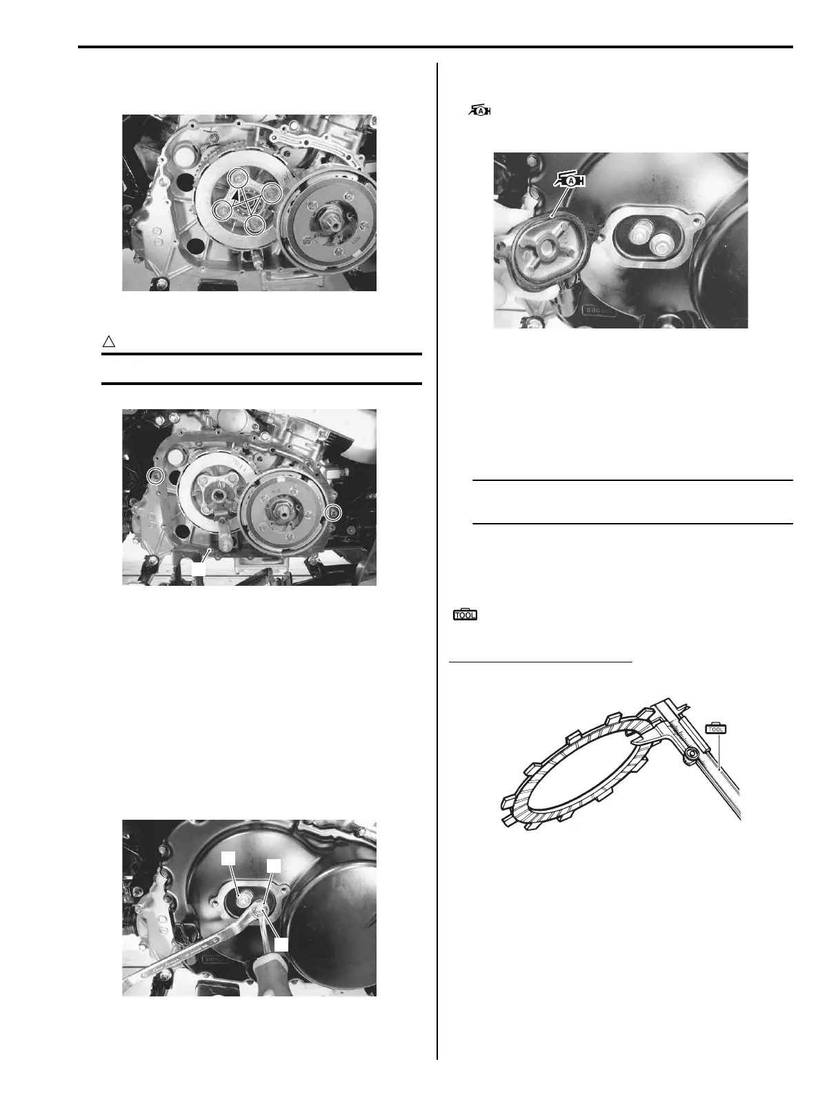
Measure the thickness of drive plates with a vernier
calipers. If the drive plate thickness is found to have
reached the limit, replace it with a new one.
Special tool
(A): 09900–20102 (Vernier calipers (1/20 mm,
200 mm))
Clutch drive plate thickness
Service limit: 2.62 mm (0.103 in)
I827H1530020-01
4
I827H1530021-01
1
3
2
I827H1530022-01
I827H1530023-02
(A
I649G1530056-03
 Loading...


