1I-9 Starting System:
2) Disconnect the gear position switch coupler (1).
3) Inspect the gear position switch for continuity with
the tester. If any abnormality is found, replace the
gear position switch with a new one. Refer to “Gear
Position (GP) Switch Removal and Installation (LT-
A400/F) in Section 3C (Page 3C-16)”.
Special tool
: 09900–25008 (Multi-circuit tester set)
Tester knob indication
Continuity ( )
4) After finishing the gear position switch inspection,
reinstall the removed parts.
LT-F400/F
Inspect the gear position switch in the following
procedures:
1) Remove the left side cover and left footrest
mudguard. Refer to “Exterior Parts Removal and
Installation in Section 9D (Page 9D-3)”.
2) Disconnect the gear position switch coupler (1).
3) Inspect the gear position switch for continuity with
the tester. If any abnormality is found, replace the
gear position switch with a new one. Refer to “Gear
Position (GP) Switch Removal and Installation (LT-
F400/F) in Section 5B (Page 5B-7)”.
Special tool
: 09900–25008 (Multi-circuit tester set)
Tester knob indication
Continuity ( )
4) After finishing the gear position switch inspection,
reinstall the removed parts.
Starter Clutch Removal and Installation
B827H11906014
Removal
1) Drain engine oil. Refer to “Engine Oil and Filter
Replacement in Section 0B (Page 0B-7)”.
2) Remove the generator cover. Refer to “Generator
Removal and Installation in Section 1J (Page 1J-5)”.
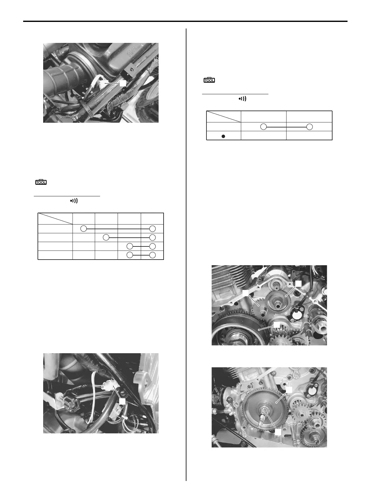
3) Remove the starter idle gear No.1 (1) and No.2 (2).
4) Remove the generator rotor assembly (3). Refer to
“Generator Removal and Installation in Section 1J
(Page 1J-5)”.
5) Remove the key (4) and starter driven gear (5).
1
I827H1190029-01
Color
R
N
H
L
Position
R
WBl B
I827H1190030-01
1
I827H1190031-01
Color
Neutral
Position
Bl B
I827H1190032-01
2
3
1
I827H1190018-02
5
4
I827H1190019-01
 Loading...


