4A-11 Brake Control System and Diagnosis:
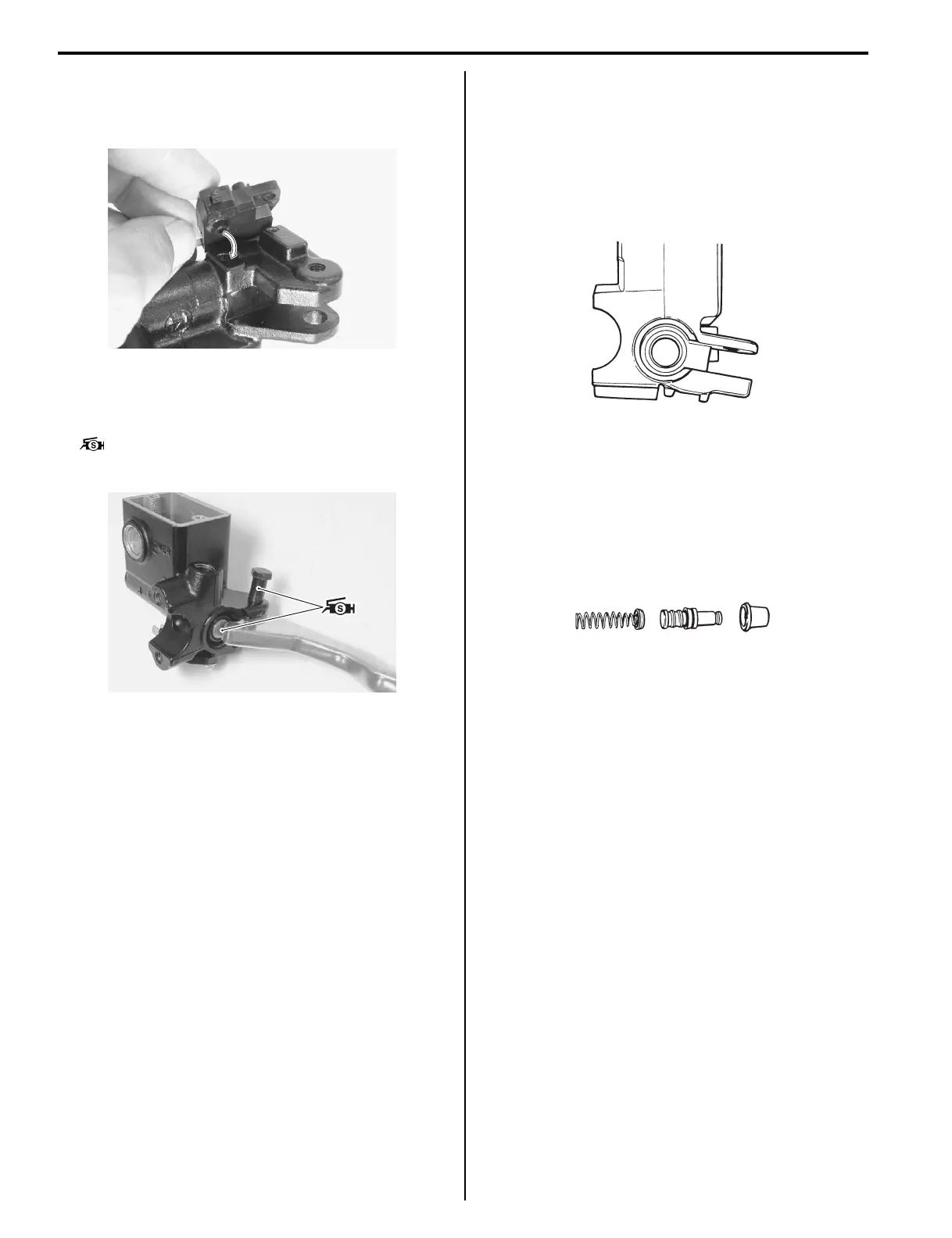
• When installing the brake light switch, align the
projection on the switch with the hole in the master
cylinder.
• Apply grease to the brake lever pivot bolt.
• Apply grease to the contact point between piston and
brake lever.
: Grease 99000–25100 (SUZUKI Silicone
Grease or equivalent)
• Tighten the pivot bolt and lock-nut to the specified
torque.
Tightening torque
Brake lever pivot bolt: 6 N·m (0.6 kgf-m, 4.5 lb-ft)
Brake lever pivot bolt lock-nut: 6 N·m (0.6 kgf-m,
4.5 lb-ft)
Front Brake Master Cylinder Parts Inspection
B827H14106016
Refer to “Front Brake Master Cylinder / Brake Lever
Disassembly and Assembly (Page 4A-10)”.
Master Cylinder
Inspect the master cylinder bore for any scratches or
other damage.
Piston
Inspect the piston surface for any scratches or other
damage.
Rubber Parts
Inspect the primary cup, secondary cup and dust boot
for wear or damage.
Parking / Rear Brake Lever Removal and
Installation
B827H14106019
Refer to “Parking / Rear Brake Lever Removal and
Installation in Section 4D (Page 4D-2)”.
I827H1410029-01
I827H1410030-01
I649G1410027-02
I649G1410028-02
 Loading...


