2C-4 Rear Suspension:
Swingarm Bushing Removal and Installation
B827H12306019
Refer to “Swingarm Removal And Installation (Page 2C-
2)”.
Removal
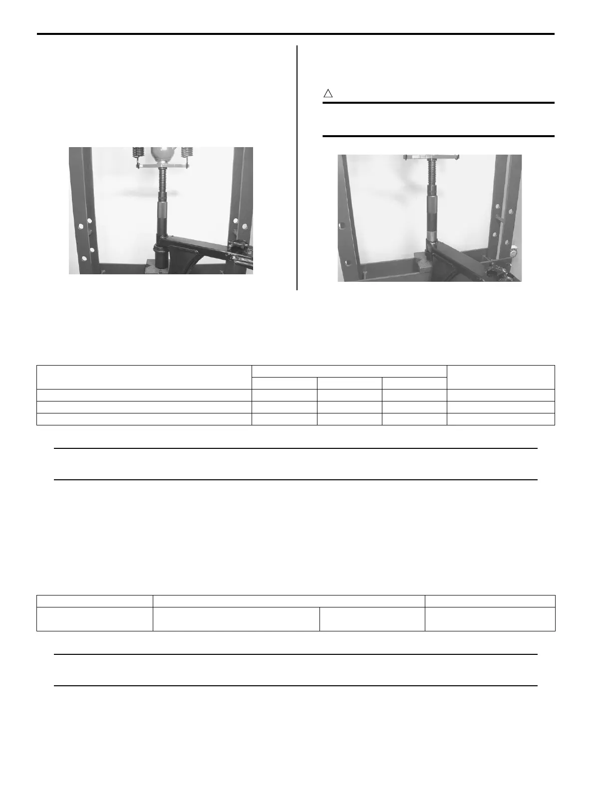
Remove the swingarm bushings using a hydraulic press
and suitable tools.
Installation
Install the swingarm bushings using a hydraulic press
and suitable tools.
CAUTION
!
The removed bushing must be replaced with
new ones.
Specifications
Tightening Torque Specifications
B827H12307001
NOTE
The specified tightening torque is also described in the following.
“Rear Suspension Components (Page 2C-1)”
Reference:
For the tightening torque of fastener not specified in this section, refer to “Tightening Torque List (LT-A400/F) in
Section 0C (Page 0C-9)”.
Special Tools and Equipment
Recommended Service Material
B827H12308001
NOTE
Required service material is also described in the following.
“Rear Suspension Components (Page 2C-1)”
I827H1230009-01
I827H1230010-01
Fastening part
Tightening torque
Note
N⋅mkgf-mlb-ft
Rear shock absorber mounting nut (upper) 35 3.5 25.5 )(Page 2C-2)
Rear shock absorber mounting nut (lower) 60 6.0 43.5 )(Page 2C-2)
Swingarm pivot nut 102 10.2 74.0 )(Page 2C-3)
Material SUZUKI recommended product or Specification Note
Thread lock cement THREAD LOCK CEMENT SUPER
1303 or equivalent
P/No.: 99000–32030 )(Page 2C-2) / )(Page 2C-
3)
 Loading...


