Body Structure: 9E-2
Footrest Removal and Installation
B827H19506003
Removal
1) Remove the footrest mudguard. Refer to “Exterior
Parts Removal and Installation in Section 9D
(Page 9D-3)”.
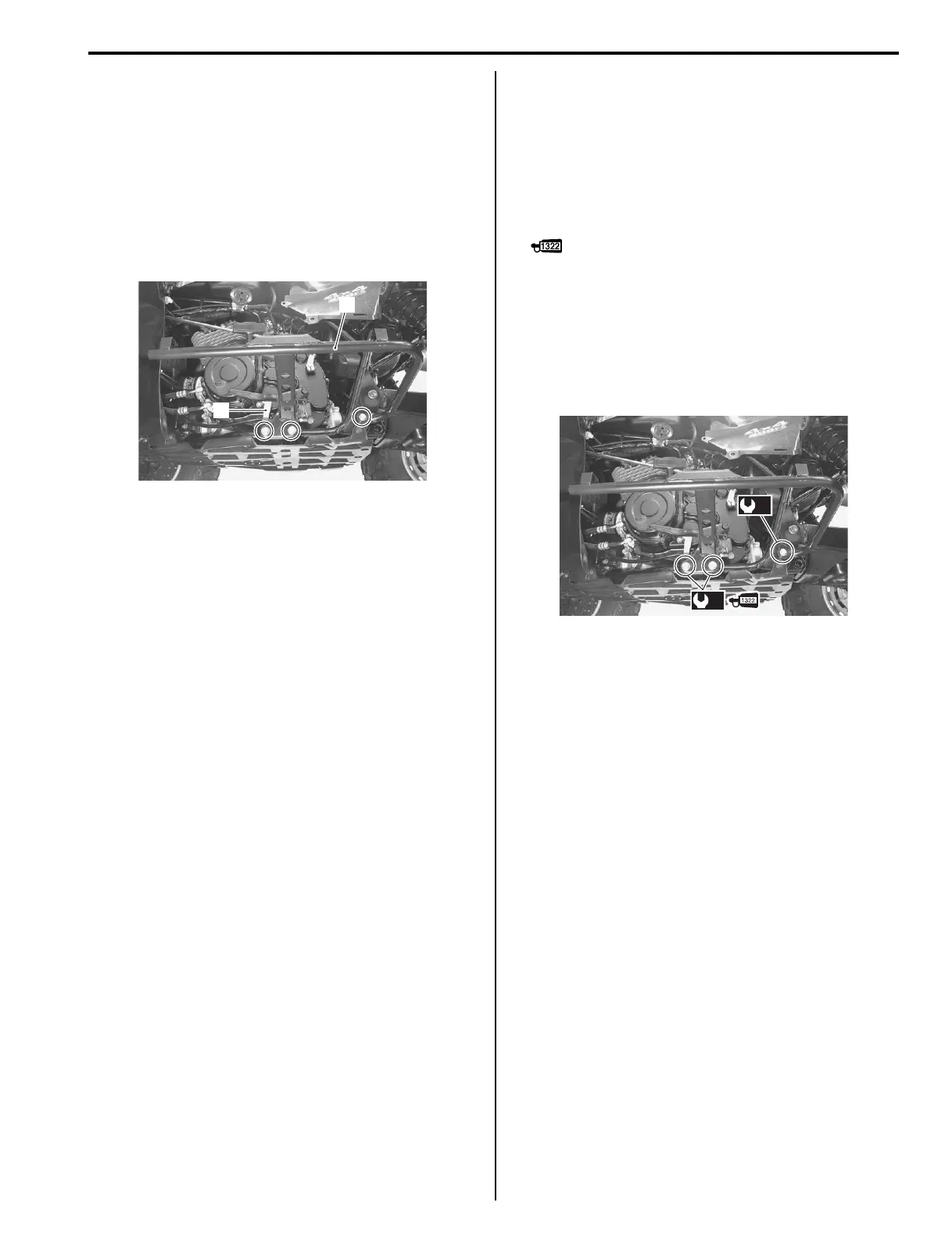
2) Remove the gearshift link arm (1) from the engine.
(LT-F400/F LH).
3) Remove the footrest (2).
4) Remove the gearshift lever assembly from the
footrest. (LT-F400/F LH). Refer to “Gearshift Lever
Removal and Installation (LT-F400/F) in Section 5B
(Page 5B-8)”.
Installation
Install the footrest in the reverse order of removal. Pay
attention to the following point:
• Install the gearshift lever assembly to the footrest. (LT-
F400/F LH). Refer to “Gearshift Lever Removal and
Installation (LT-F400/F) in Section 5B (Page 5B-8)”.
• Apply thread lock to the footrest mounting bolts (M10)
and tighten them to the special torque.
: Thread lock cement 99000–32110
(THREAD LOCK CEMENT SUPER 1322 or
equivalent)
Tightening torque
Footrest mounting bolt (M10) (a): 55 N·m (5.5 kgf-
m, 40.0 lb-ft)
Footrest mounting bolt (M8) (b): 25 N·m (2.5 kgf-
m, 18.0 lb-ft)
• Adjust the gearshift lever height. (LT-F400/F LH).
Refer to “Gearshift Lever Height Inspection and
Adjustment (LT-F400/F) in Section 5B (Page 5B-9)”.
1
2
I827H1950003-02
(a)
(b)
I827H1950004-02
 Loading...


