4A-1 Brake Control System and Diagnosis:
Brake
Brake Control System and Diagnosis
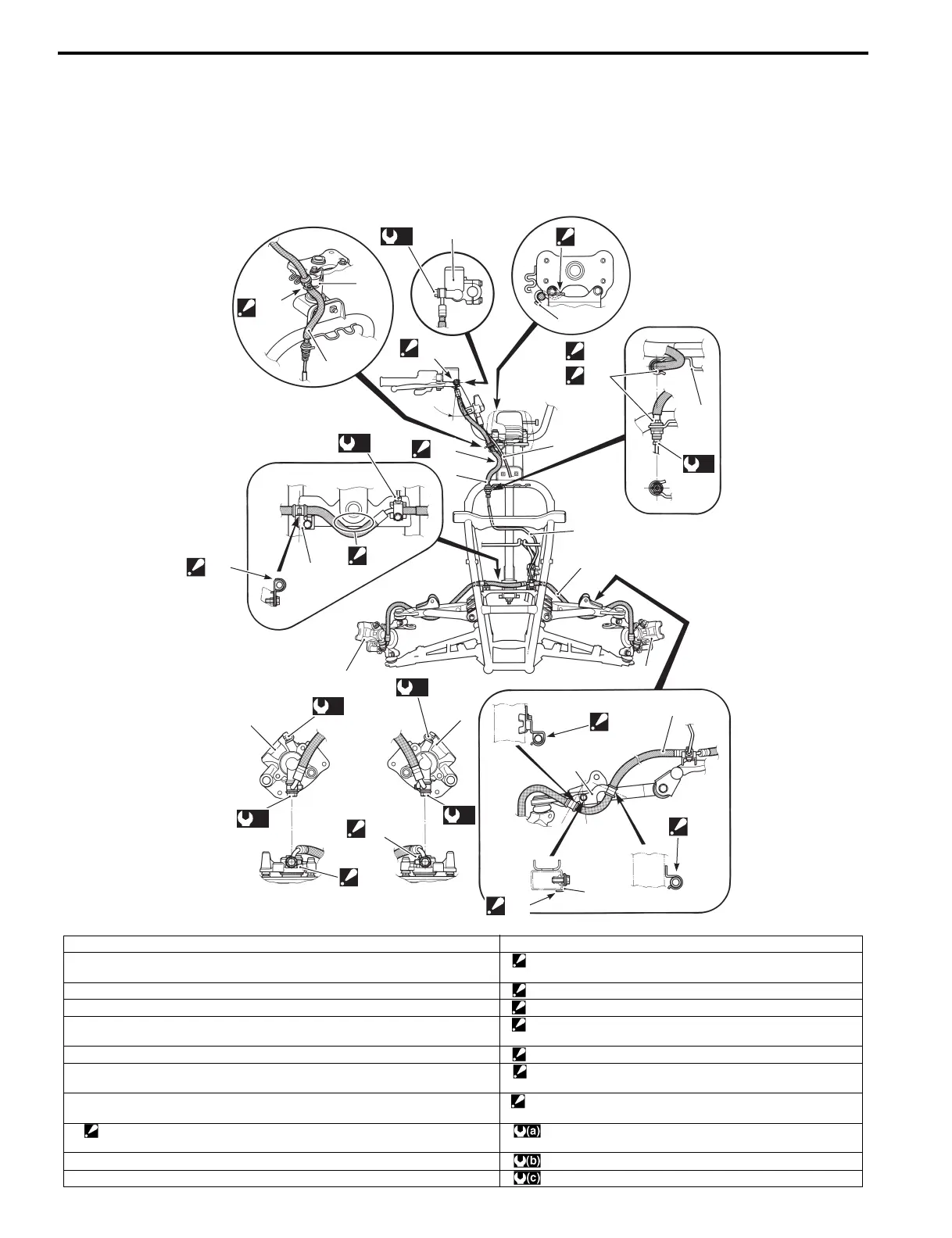
Schematic and Routing Diagram
Front Brake Hose Routing Diagram
B827H14102001
“C”
2
7
1
(a)
“D”
7
7
“E”
“C”
(b)
“A”
“a”
“B”
2
11
3
4
6
5
“C”
8
(b)
“F”
5
(c)
(a)
9
(c)
6
(a)
9
“C”
8
4
“C”
10
“G”
I827H1410035-04
1. Front brake master cylinder “a”: 21°
2. Front brake hose No. 1 “A”: After the brake hose union has contacted the reservoir bottom,
tighten the union bolt.
3. Front brake pipe “B”: Pass the brake hose in front of steering shaft plate.
4. Front brake hose No. 2 “C”: Fix the brake hose to its guide firmly.
5. Front brake caliper (RH) “D”: After the brake hose guide has contacted the speedometer
bracket, tighten the bolt.
6. Front brake caliper (LH) “E”: Face the black mark on the brake hose to forward.
7. Brake hose guide “F”: Check that there is at least 6 mm (0.2 in) of clearance between
the brake hose and steering shaft.
8. Clamp “G”: After the hose clamp stopper has contacted the suspension
arm bottom firmly, tighten the bolt.
9. Stopper
: After the brake hose union has contacted the stopper, tighten the union bolt.
: 23 N⋅m (2.3 kgf-m, 16.5 lb-ft)
10. Hose clamp stopper : 16 N⋅m (1.6 kgf-m, 11.5 lb-ft)
11. Transfer cable (LT-A400F, LT-F400F) : 6 N⋅m (0.6 kgf-m, 4.5 lb-ft)
 Loading...


