1E-13 Engine Lubrication System:
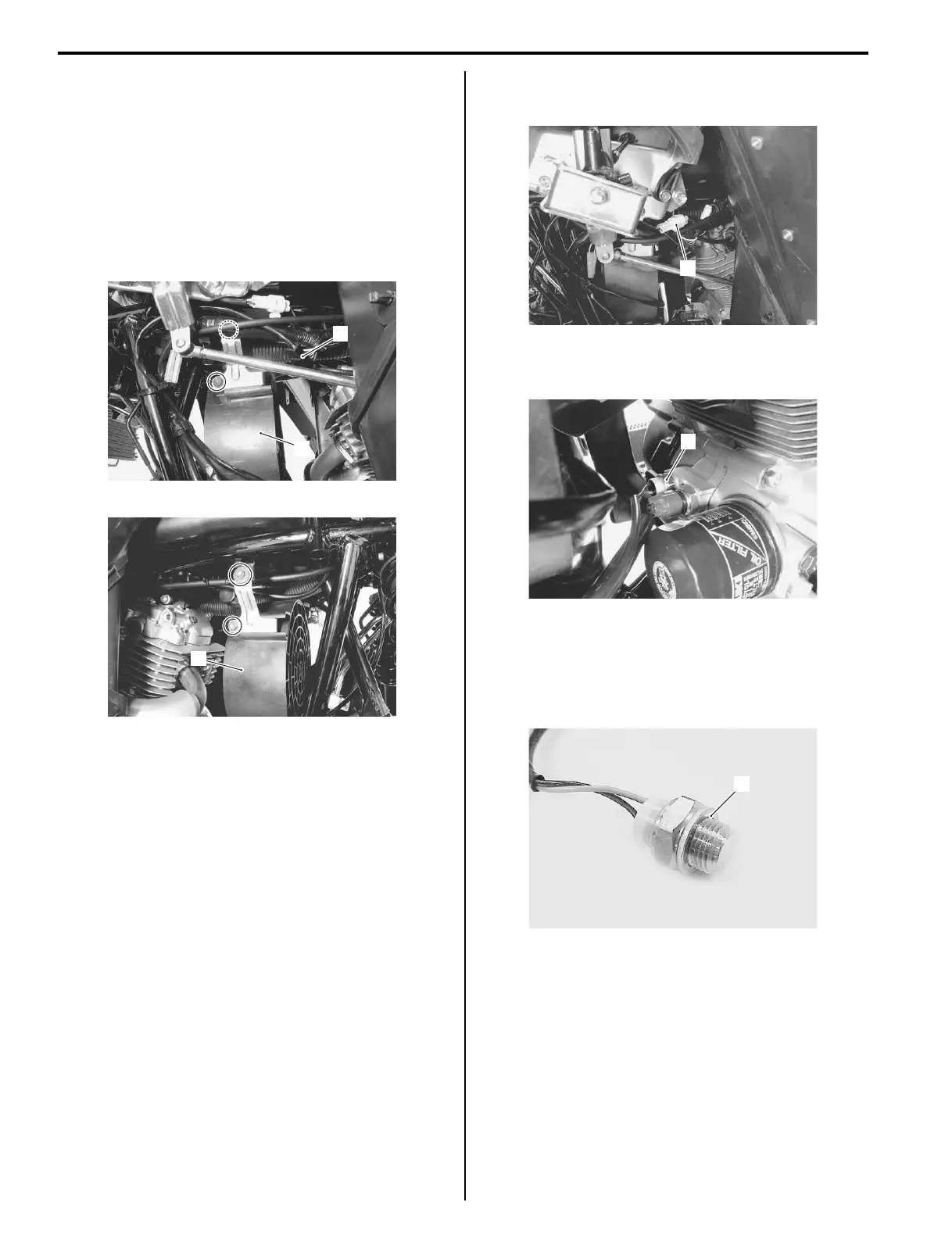
Cooling Fan Removal and Installation
B827H11506014
Removal
1) Remove the left inner fenders. Refer to “Exterior
Parts Removal and Installation in Section 9D
(Page 9D-3)”.
2) Disconnect the cooling fan motor lead wire coupler
(1).
3) Remove the cooling fan bracket bolts, left and right
and remove the cooling fan (2).
Installation
Install the cooling fan in the reverse order of removal.
Cooling Fan Thermo-switch Removal and
Installation
B827H11506015
Removal
1) Remove the left inner fender. Refer to “Exterior Parts
Removal and Installation in Section 9D (Page 9D-
3)”.
2) Disconnect the cooling fan thermo-switch lead wire
coupler (1).
3) Place a rag under the switch and remove the cooling
fan thermo-switch (1).
Installation
Installation is in the reverse order of removal. Pay
attention to the following points:
• Install new seal washer (1).
• Tighten the engine oil temperature switch to the
specified torque.
Tightening torque
Cooling fan thermo-switch: 20 N·m (2.0 kgf-m,
14.5 lb-ft)
• Check engine oil level or pour engine oil if necessary.
Refer to “Engine Oil and Filter Replacement in
Section 0B (Page 0B-7)”.
2
1
I827H1150035-01
2
I827H1150036-01
1
I827H1150037-01
1
I827H1150038-01
1
I827H1150039-01
 Loading...


