E - Checking installation position of sender wheel on crankshaft
⇒ Page 176.
F - Re-pressing sender wheel ⇒ Page 177.
2.5.1 Pressing out sealing flange with sender
wheel
Note
For the sake of clarity, the work is performed with the engine re-
moved.
– Remove flywheel ⇒ Page 167, Assembly overview - sealing
flanges and flywheel.
– Remove intermediate plate.
– Set engine to TDC for no. 1 cylinder ⇒ Page 210, Removing
and installing toothed belt.
– Drain engine oil ⇒ Page 245.
Note
Observe environmental regulations for disposal.
– Remove sump ⇒ Page 244.
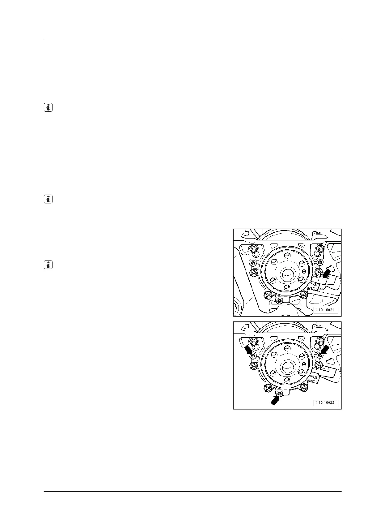
– Remove engine speed sender -G28- -arrow- using a com-
mercially available ball-ended hex key socket.
– Unscrew sealing flange securing bolts.
Note
Sealing flange and sender wheel are pressed off the crankshaft
together using three M6 x 35 mm bolts.
– Screw three M6 x 35 mm bolts into threaded holes -arrows-
of sealing flange.
– Screw bolts alternately (max.
1
/
2
turn (180 °) for each bolt)
into sealing flange and press sealing flange together with
sender wheel off crankshaft.
Industriemotoren - Industrial Engines 2009 ▶
Workshop Manual for Diesel Engine (2.0 l/36-75 kW_EA 189) 05.2015
3
2 Removing and installing sealing flange and flywheel
171
 Loading...