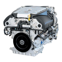
3.1 Markings on air mass meter and on el-
bow of the intake connecting pipe, view
from turbocharger end
– To ease installation, both the air mass meter -item 1- and the
elbow of the intake connecting pipe -item 2- and -item 3- are
provided with markings.
– To make sure that the air mass meter is properly positioned,
align marking -1- on air mass meter with marking -2- on el-
bow of the intake connecting pipe.
– Marking -2- is located below marking -3- on the same level
as the bracket.
3.2 Checking charge pressure control sole-
noid valve -N75-, engine codes CJDA,
CJDD, CPYA, CPYB, CPYC, CPYD,
CPYE
Special tools and workshop equipment required
◆ Connect vehicle diagnosis, testing and information system
-VAS 5051/B- using diagnostic cable -VAS 5051B/1-.
◆ Hand multimeter -V.A.G 1526- or multimeter -V.A.G 1715-
◆ Auxiliary measuring set -V.A.G 1594D-
◆ Test box -V.A.G 1598/42- with adapter cable
-V.A.G 1598/39-1-
◆ Current flow diagram
Test prerequisites
● Engine running at idling speed
● Fuses must be OK.
● The battery voltage must be at least 11.5 V.
● All electrical consumers must be switched off.
● Earth connections OK
● Coolant temperature must be at least 80°C, ⇒ display group
1, display zone 4.
Test procedure
– Carry out final control diagnosis, and activate charge pres-
sure control solenoid valve -N75- ⇒ Page 89, final control di-
agnosis.
The display in display zone 2 must fluctuate between “OFF” and
“ON”:
Industriemotoren - Industrial Engines 2009 ▶
Workshop Manual for Diesel Engine (2.0 l/36-75 kW_EA 189) 05.2015
3
3 Checking components and functions
341
 Loading...