– Check wiring between test box and connector for open cir-
cuit referring to current flow diagram.
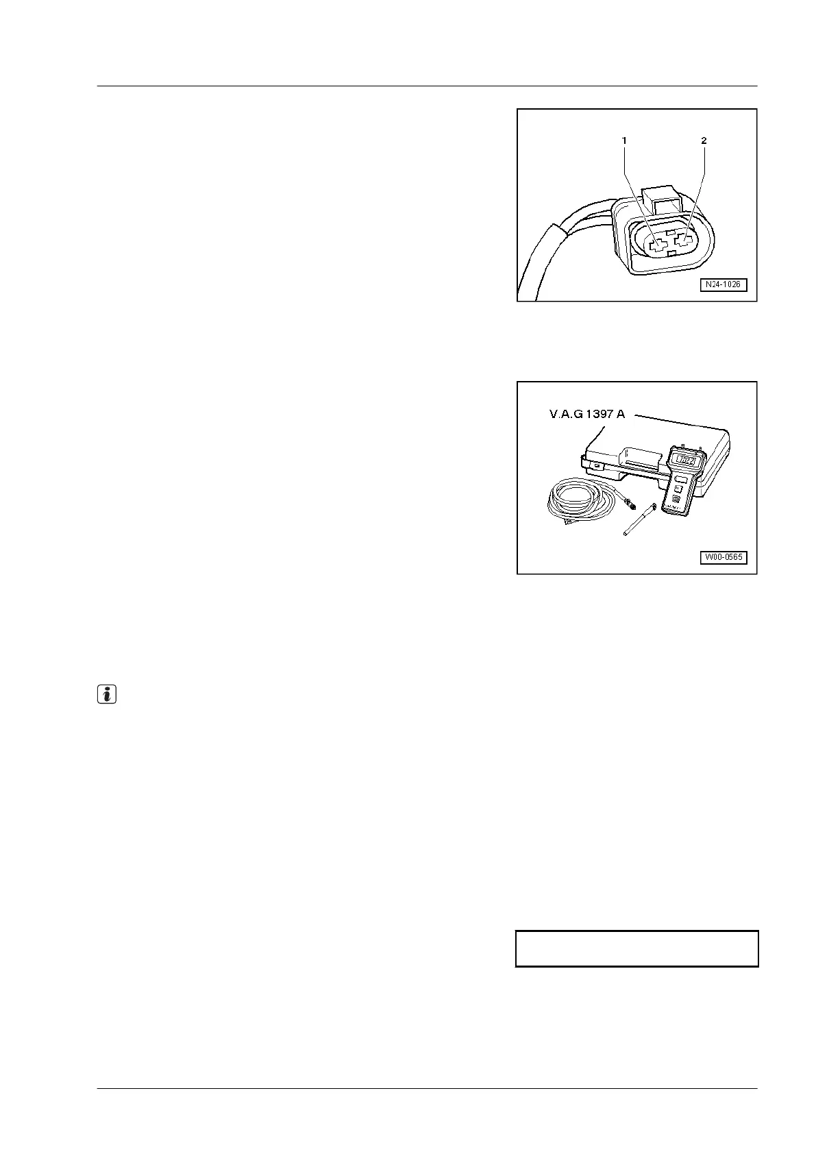
◆ Contact 2 + socket 20
● Cable resistance: max. 2.0 Ω.
– Additionally check wires for short to one another. Specifica-
tion: ∞ Ω
If no wiring fault is detected and voltage supply is OK:
– Renew engine control unit -J623- ⇒ Page 418.
3.3 Checking charge pressure sender -G31-
Special tools and workshop equipment required
◆ Turbocharger tester -V.A.G 1397 A-
◆ Hand multimeter -V.A.G 1526- or multimeter -V.A.G 1715-
◆ Auxiliary measuring set -V.A.G 1594D-
◆ Test box -V.A.G 1598/42- with adapter cable
-V.A.G 1598/39-2-
◆ Current flow diagram
Test prerequisites
● Fuses must be OK.
● The battery voltage must be at least 11.5 V.
● All electrical consumers must be switched off.
● Earth connections OK
Test procedure
Note
◆ The charge pressure sender -G31- and intake air tempera-
ture sender -G42- are installed in one common housing in
the charge air pipe.
◆ Only gold-plated contacts may be used when repairing con-
tacts in connector.
– Switch on ignition.
– Connect vehicle diagnostic tester, and select engine control
unit. ⇒ Page 23
– Select diagnosis function “011-Read measured value block”.
– Select “Display group 11”.
Indicated on display:
– Check specification for charge pressure in display zone 3.
– Compare displayed charge pressure (actual) with display on
turbocharger tester -V.A.G 1397 A-. Specification: displayed
pressure values must correspond (tolerance ± 50 mbar).
Display group 11
xxxx rpm xxxx mbar 978 mbar xxx%
Industriemotoren - Industrial Engines 2009 ▶
Workshop Manual for Diesel Engine (2.0 l/36-75 kW_EA 189) 05.2015
3
3 Checking components and functions
343
 Loading...