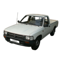
– Disconnect connector from fuel temperature sender -G81-
-arrow-, loosen clamp -1-, and pull fuel supply line off high-
pressure pump.
– Unscrew securing bolts of supplementary fuel pump -V393-.
Installing
Install in reverse order. In the process, note the following:
◆ Route fuel hoses without kinking.
◆ Ensure that fuel hose connections are tight.
◆ Do not interchange supply and return lines.
◆ Clip fuel and coolant hoses into retainers again.
2 Checking components and func-
tions
WARNING
Adhere to the general safety regulations and the notes on
repair work on the engine! ⇒ Page 1
The described component checks and functional checks are ap-
plicable for the series components and the current flow dia-
grams as of page ⇒ Page 486, current flow diagrams.
If components and electric circuits differ, observe the notes of
the respective industrial engine customer.
Checking supplementary fuel pump -V393- (inline electronic
fuel pump) ⇒ Page 314.
Checking accelerator pedal position sender -G79-, if fitted
⇒ Page 316.
2.1 Checking supplementary fuel pump
-V393- (inline electronic fuel pump)
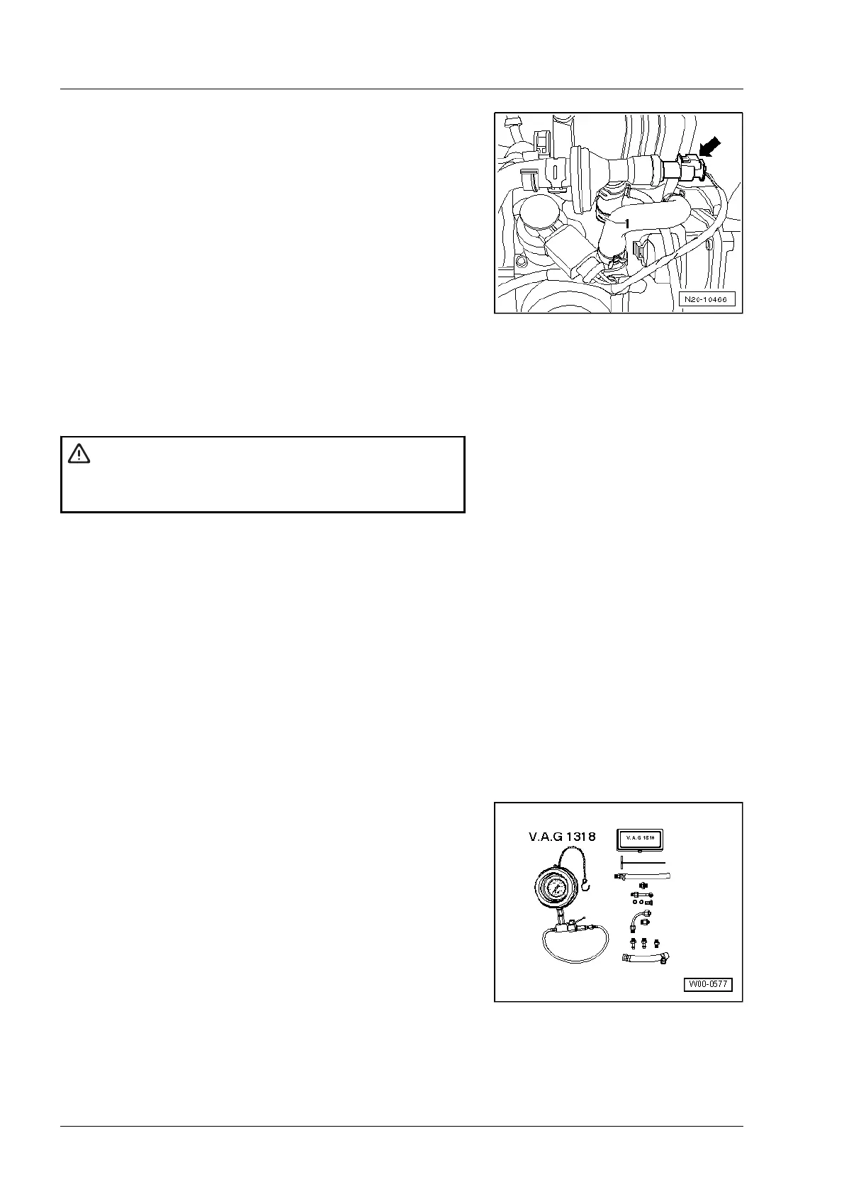
Special tools and workshop equipment required
◆ K-Jetronic pressure tester -V.A.G 1318-
3
Industriemotoren - Industrial Engines 2009 ▶
Workshop Manual for Diesel Engine (2.0 l/36-75 kW_EA 189) 05.2015
314
Repair Group 20 - Fuel supply system
 Loading...