Bearing shells - installation position ⇒ Page 186.
Checking piston projection at TDC ⇒ Page 187.
Piston and cylinder dimensions ⇒ Page 188
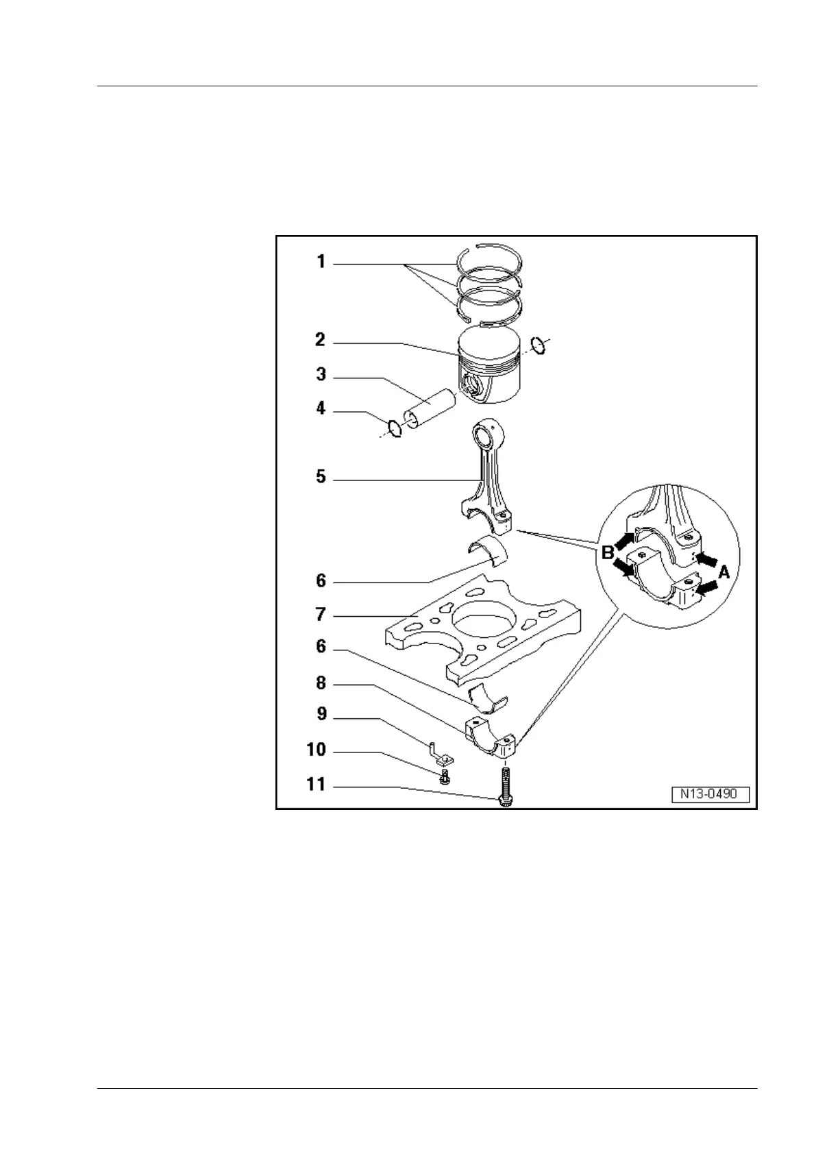
4.1 Assembly overview - pistons and conrods
1 - Piston rings
q Offset gaps by 120°.
q Use piston ring pli-
ers to remove and
install.
q “TOP” faces to-
wards piston crown.
q Checking ring gap
⇒ Fig. on page 184.
q
Checking ring-to-
groove clearance
⇒ Fig. on page 185.
2 - Piston
q
Mark installation po-
sition and cylinder
number.
q
Installation position
and allocation of
piston to cylinder
⇒ Fig. on page 185.
q Arrow on piston
crown points to belt
pulley end.
q Install using piston
ring clamp.
q If piston skirt is
cracked, renew pis-
ton.
q Checking piston
projection at TDC
⇒ Page 187.
3 - Piston pin
q If difficult to remove,
heat piston to 60°C
q Remove and install using drift -VW 222 a-.
4 - Retaining ring
5 - Conrod
q Mark with cylinder number -A-.
q Installation position: Marking -B- faces towards pulley end.
q With industrially cracked conrod cap.
q Separate new conrod ⇒ Page 185
6 - Bearing shell
q Note installation position ⇒ Page 186
q Do not interchange used bearing shells.
Industriemotoren - Industrial Engines 2009
▶
Workshop Manual for Diesel Engine (2.0 l/36-75 kW_EA 189) 05.2015
3
4 Dismantling and assembling pistons and conrods
183
 Loading...