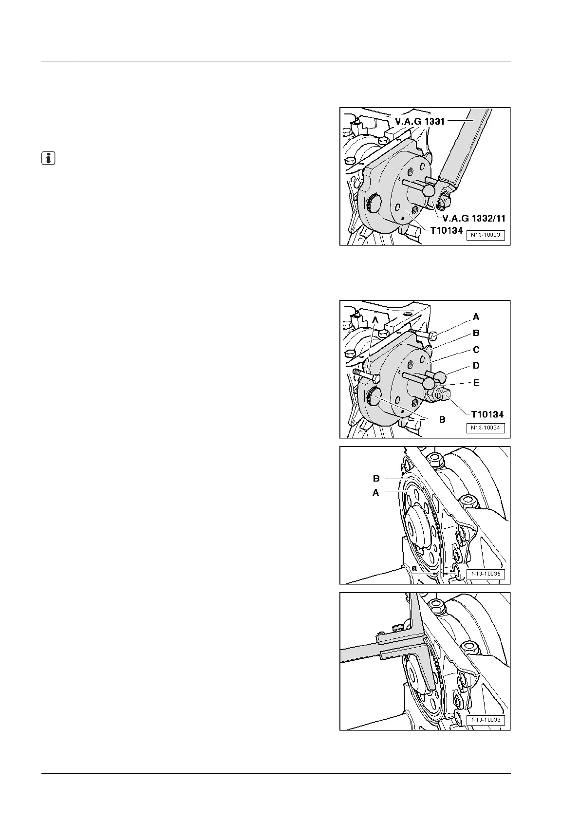
2.5.6 D - Pressing sender wheel onto crankshaft
flange using assembly tool -T10134-
– Tighten hexagon nut of assembly tool -T10134- to 35 Nm us-
ing torque wrench -V.A.G 1331- and tool insert, 24 mm
-V.A.G 1332/11-.
Note
After the hexagon nut is tightened to 35 Nm, there must still be
a small air gap between cylinder block and sealing flange.
2.5.7 E - Checking installation position of sender
wheel on crankshaft
– Screw hexagon nut -E- to end of threaded spindle.
– Remove the two bolts -A- from cylinder block.
– Loosen the two hexagon socket head bolts.
– Screw the three knurled screws -B- out of sealing flange.
– Remove assembly tool -T10134-.
– Remove sealing lip support ring.
– The sender wheel is in the correct installation position on the
crankshaft if a gap -a- = 0.5 mm exists between crankshaft
flange -A- and sender wheel -B-.
– Set vernier gauge on crankshaft flange.
– Measure distance -a- between crankshaft flange and sender
wheel.
If measurement -a- is too small:
– Re-press sender wheel ⇒ Page 177.
If dimension -a- is attained:
– Tighten new securing bolts for sealing flange to 15 Nm using
alternate and diagonal sequence.
3
Industriemotoren - Industrial Engines 2009 ▶
Workshop Manual for Diesel Engine (2.0 l/36-75 kW_EA 189) 05.2015
176
Repair Group 13 - Crankshaft group
 Loading...