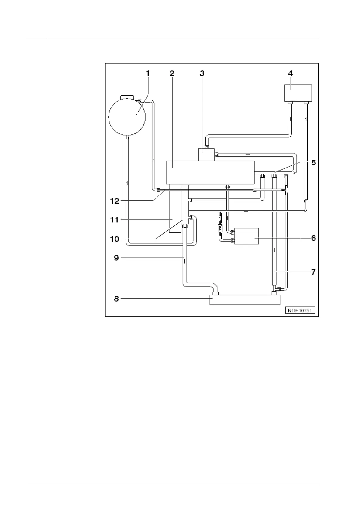
1.3 Coolant hose schematic diagram
1 - Expansion tank
2 - Cylinder head/cylin-
der block
3 - Exhaust gas recircu-
lation valve
4 - Heat exchanger for
heater, optional
5 - Connection
q On cylinder head.
6 - Engine oil cooler
7 - Coolant return hose
q To radiator
8 - Radiator
9 - Coolant supply hose
q To thermostat with
4/2-way valve
10 - 4/2-way valve
q Removing and in-
stalling 4/2-way
valve ⇒ Page 290.
11 - Coolant pump
12 - Breather pipe
q
To expansion tank.
1.4 Cooling system: Check frost protection
and coolant level
◆ Checking frost protection, replenishing coolant additive if
necessary ⇒ Page 281
◆ Checking coolant level, replenishing coolant additive if nec-
essary ⇒ Page 282
3
Industriemotoren - Industrial Engines 2009 ▶
Workshop Manual for Diesel Engine (2.0 l/36-75 kW_EA 189) 05.2015
280
Repair Group 19 - Cooling
 Loading...