Actual signals and parameters 145
Parameters in the short parameter view
Parameters in the short parameter view
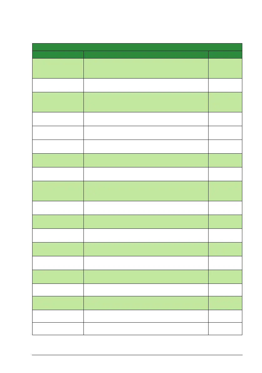
No. Name/Value Description Default
11 REFERENCE
SELECT
Panel reference type, external control location selection
and external reference sources and limits. See Group
11: Reference select in the list of all parameters.
1105 REF1 MAX Defines the maximum value for external reference
REF1.
E: 50.0 Hz
U: 60.0 Hz
12 CONSTANT
SPEEDS
Constant speed (drive output frequency) selection and
values. See Group 12: Constant speeds in the list of all
parameters.
1202 CONST
SPEED 1
Defines constant drive output frequency 1. E: 5.0 Hz
U: 6.0 Hz
1203 CONST
SPEED 2
Defines constant drive output frequency 2. E: 10.0 Hz
U: 12.0 Hz
1204 CONST
SPEED 3
Defines constant drive output frequency 3. E: 15.0 Hz
U: 18.0 Hz
13 ANALOG INPUTS Analog input signal processing. See Group 13:
Analogue inputs in the list of all parameters.
1301 MINIMUM AI1 Defines the minimum %-value that corresponds to
minimum mA/(V) signal for analog input AI1.
1.0%
14 RELAY OUTPUTS Status information indicated through relay output, and
relay operating delays. See Group 14: Relay outputs in
the list of all parameters.
1401 RELAY
OUTPUT 1
Selects a drive status indicated through relay output
RO 1.
FAULT(-1)
16 SYSTEM
CONTROLS
Parameter view, Run Enable, parameter lock etc. See
Group 16: System controls in the list of all parameters.
1611 PARAMETER
VIEW
Selects the parameter view, in other words, which
parameters are shown on the control panel.
SHORT
VIEW
20 LIMITS Drive operation limits. See Group 20: Limits in the list of
all parameters.
2008 MAXIMUM
FREQ
Defines the maximum limit for the drive output
frequency.
E: 50.0 Hz
U: 60.0 Hz
21 START/STOP Start and stop modes of the motor. See Group 21:
Start/Stop in the list of all parameters.
2102 STOP
FUNCTION
Selects the motor stop function. COAST
22 ACCEL/DECEL Acceleration and deceleration times. See Group 22:
Accel/Decel in the list of all parameters.
2202 ACCELER
TIME 1
Defines the acceleration time 1. 5.0 s
2203 DECELER
TIME 1
Defines the deceleration time 1. 5.0 s

 Loading...


