90 Application macros
Internal timer
This macro configures for applications where a built-in timer starts and stops the
motor. When the variable speed pump reaches a maximum speed limit, auxiliary
pumps start as needed. When using direct speed reference in AUTO mode or
process PID, see section General considerations on page 80.
Momentarily activating digital input 3 (DI3) provides a boost function which operates
the motor. See Group 36: Timed functions for more information on setting up timers.
For more information see Default values with different macros on page 279.
Parameters changed relative to HVAC default
Parameter Value
Parameter Value
9902 APPLIC MACRO 8 (INT TIMER) 1609 START ENABLE 2 5 (DI5)
1001 EXT1 COMMANDS 11 (TIMER1)
3207 SUPERV 3 PARAM 0103 (OUTPUT FREQ)
1002 EXT2 COMMANDS 11 (TIMER1)
3601 TIMERS ENABLE 1 (DI1)
1201 CONST SPEED SEL 0 (NOT SEL)
3622 BOOST SEL 3 (DI3)
1401 RELAY OUTPUT 1 7 (STARTED)
3626 TIMER 1 SRC 31 (P1+2+3+4+B)
1601 RUN ENABLE 2 (DI2)
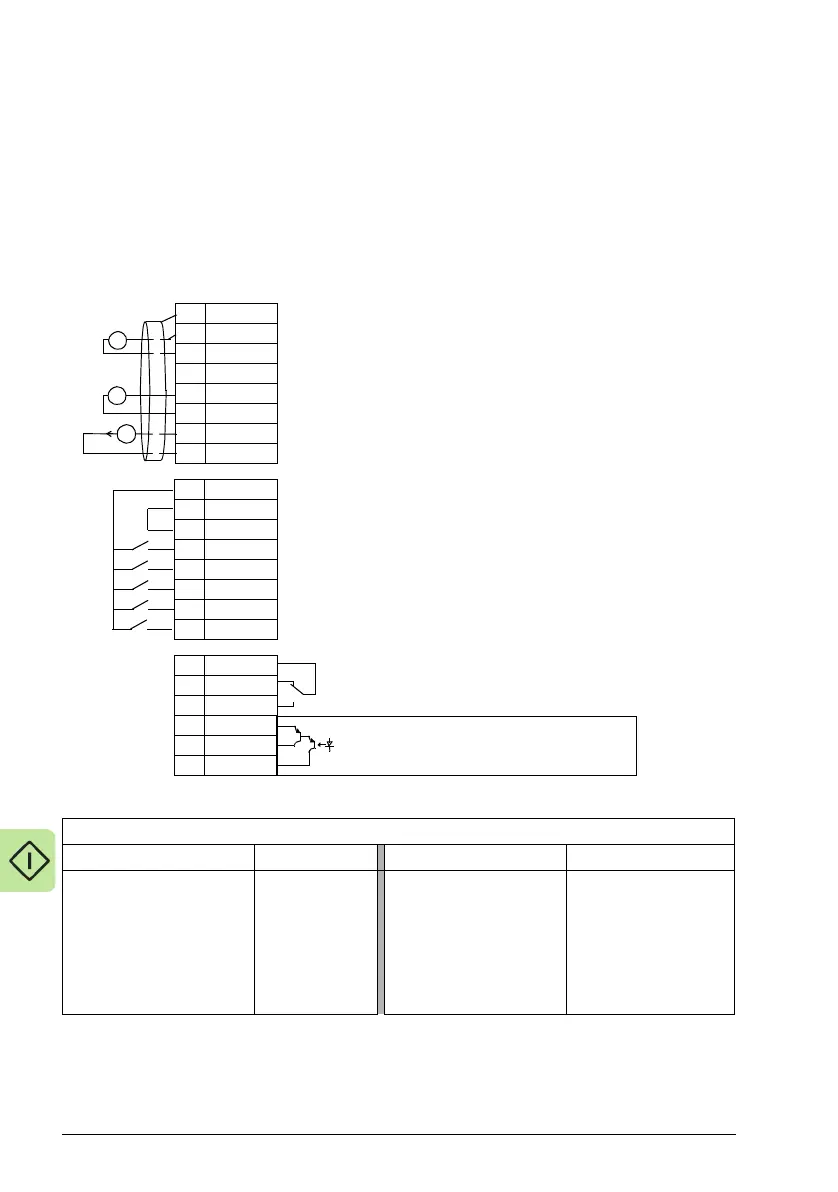
1SCR
2AI1
3AGND
410V
5AI2
6AGND
7AO1
8AGND
924V
10 GND
11 DCOM
12 DI1
13 DI2
14 DI3
15 DI4
16 DI5
17 RO1C
18 RO1A
19 RO1B
20 DOSRC
21 DOOUT
22 DOGND
External reference 0(2)…10 V or 0(4)…20 mA
Reference voltage 10 VDC
Output frequency: 0(4)…20 mA
Start/Stop: Activate to start drive
Run permissive: Deactivate to stop drive (P 1601)
Timer Override: Activate to start drive
Safety interlock1: Deactivate to stop drive (P 1608)
Safety interlock2: Deactivate to stop drive (P 1609)
Relay output 1 (P 1401)
Default operation: Started =>17 connected to 19
Digital output, max. 100 mA (P 1805)
No fault [Fault(-1)] =>20 connected to 22
X1A
Analog input circuit common
PID feedback: 0(2)…10 V or 0(4)…20 mA
Analog output circuit common
Auxiliary voltage output +24 VDC
Auxiliary voltage output common
Digital input common for all
Signal cable shield (screen)
Analog input circuit common
+
mA
+
X1B

 Loading...


