Technical data 391
Size of copper conductor in cablings
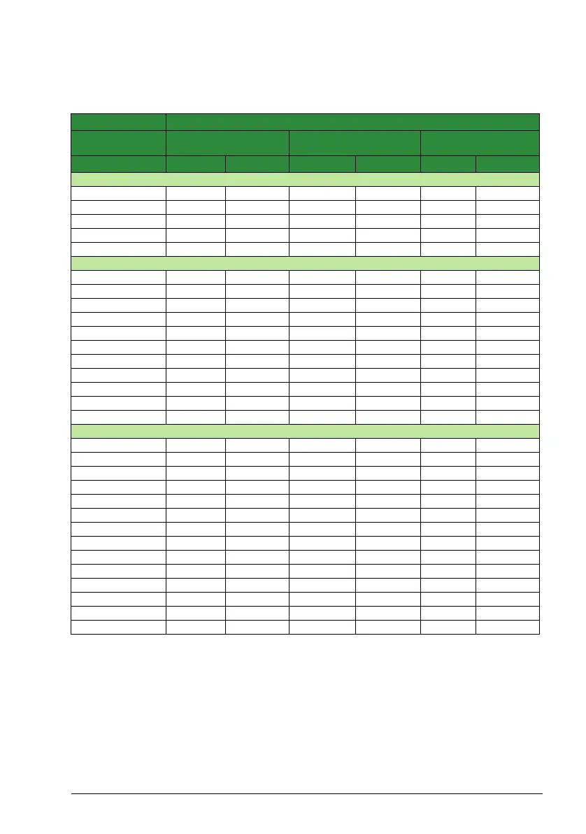
Cable dimensioning for rated currents (I
1N
) is shown in the table below.
Type Size of copper conductor in cablings
ACS320- Supply
(U1, V1, W1)
Motor
(U2, V2, W2)
PE
x = E/U
1)
mm
2
AWG mm
2
AWG mm
2
AWG
1-phase
01x-02A4-2 2.5 14 0.75 18 2.5 14
01x-04A7-2 2.5 14 0.75 18 2.5 14
01x-06A7-2 2.5 10 1.5 14 2.5 10
01x-07A5-2 2.5 10 1.5 14 2.5 10
01x-09A8-2 6 10 2.5 12 6 10
3-phase
03x-02A6-2 2.5 14 1.5 14 2.5 14
03x-03A9-2 2.5 14 1.5 14 2.5 14
03x-05A2-2 2.5 14 1.5 14 2.5 14
03x-07A4-2 2.5 12 1.5 14 2.5 12
03x-08A3-2 2.5 12 1.5 14 2.5 12
03x-10A8-2 2.5 12 2.5 12 2.5 12
03x-14A6-2 6.0 10 6 10 6.0 10
03x-19A4-2 6.0 10 6 10 6.0 10
03x-26A8-2 10.0 8 10 8 10.0 8
03x-34A1-2 16.0 6 16 6 16.0 6
03x-50A8-2 25.0 2 25 2 16.0 4
3-phase
03x-01A2-4 2.5 14 1.5 14 2.5 14
03x-01A9-4 2.5 14 1.5 14 2.5 14
03x-02A4-4 2.5 14 1.5 14 2.5 14
03x-03A3-4 2.5 12 1.5 14 2.5 12
03x-04A1-4 2.5 12 1.5 14 2.5 12
03x-05A6-4 2.5 12 1.5 14 2.5 12
03x-07A3-4 2.5 12 1.5 14 2.5 12
03x-08A8-4 2.5 12 2.5 12 2.5 12
03x-12A5-4 6.0 10 6 10 6.0 10
03x-15A6-4 6.0 8 6 8 6.0 8
03x-23A1-4 10.0 8 10 8 10.0 8
03x-31A0-4 16.0 6 16 6 16.0 6
03x-38A0-4 25.0 4 16 4 16.0 4
03x-44A0-4 25.0 4 25 4 16.0 4
1)
E = EMC filter connected (metal EMC filter screw installed),
U = EMC filter disconnected (plastic EMC filter screw installed), default configuration for the U.S.

 Loading...


