246 Actual signals and parameters
Group 44: Pump protection
This group defines the parameters used for the set-up of pump protection.
Group 44: Pump protection
Code Description Range Resolution Default S
4401
INLET PROT CTRL
NOT SEL
Enables, and selects the mode of, the primary supervision of pump/fan inlet pressure.
Note: Inlet protection is active only when the active reference is PID.
0 = NOT SEL – Primary inlet pressure supervision not used.
1 = ALARM – Detection of low inlet pressure generates an alarm on the control panel
display.
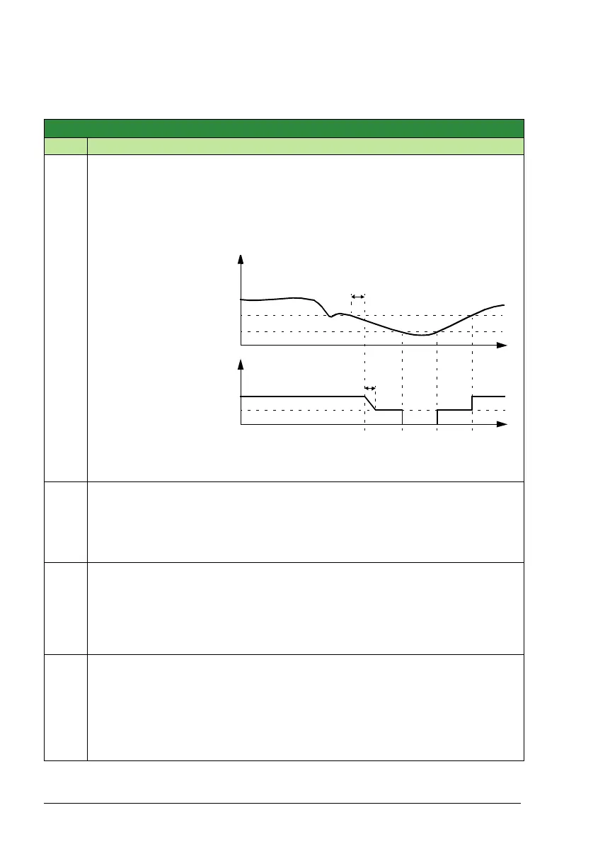
2 = PROTECT – Detection
of low inlet pressure
generates an alarm on
the control panel
display. The output of
the PI controller is
ramped down
(according to
parameter 4417 PID
OUT DEC TIME) to the
forced reference (set
by parameter 4008
INLET FORCED REF).
The drive will revert to
the original reference if
the pressure
subsequently exceeds
the supervision level.
The diagram describes the inlet pressure supervision function.
3 = FAULT – Detection of low inlet pressure trips the drive on a fault.
4402
AI MEASURE INLET
NOT SEL
Selects the analog input for pump/fan inlet pressure supervision.
0 = NOT SEL – No analog input selected.
1 = AI1 – Pump/fan inlet pressure monitored through analog input AI1.
2 = AI2 – See selection AI1.
4403
AI IN LOW LEVEL
0.00 … 100.00% 1 = 0.01% 0.00%
Sets the supervision limit for the primary inlet pressure measurement. If the value of
the selected input falls below this limit, the action defined by parameter 4401 INLET
PROT CTRL is taken after the delay set by parameter 4407 INLET CTRL DLY expires.
The range corresponds to 0…10 V or 0…20 mA on the analog input. With a bipolar
input, the absolute input value is considered.
4404
VERY LOW CTRL
NOT SEL
Enables, and selects the mode of, the secondary inlet pressure supervision function.
The function uses the analog input selected by parameter 4402 AI MEASURE INLET.
0 = NOT SEL – Secondary inlet pressure supervision not used.
1 = STOP – Detection of very low inlet pressure stops the drive. The drive will start
again if the pressure exceeds the supervision level.
2 = FAULT – Detection of very low inlet pressure trips the drive on a fault.
Measured inlet
pressure
PFA reference
(EXT 2)
4403
4405
4407
4408
t
t
4417

 Loading...


