EasyManua.ls Logo

ABB ACS320 User Manual

ABB ACS320
442 pages
To Next Page IconTo Next Page
To Previous Page IconTo Previous Page
Page #208 background imageLoading...
Page #208 background image
208 Actual signals and parameters
Group 31: Automatic reset
This group defines conditions for automatic resets. An automatic reset occurs after a
particular fault is detected. The drive holds for a set delay time, then automatically
restarts. You can limit the number of resets in a specified time period, and you can set
up automatic resets for a variety of faults.
3023
WIRING FAULT
0, 1 1 1
Selects how the drive reacts when incorrect input power and motor cable connection
is detected (ie, the input power cable is connected to the motor connection of the
drive).
0 = DISABLE No action.
1 = ENABLE – The drive trips on fault 0035 OUTP WIRING.
3027
OPTION COM LOSS
0, 1 1 1
Selects how the drive reacts when the MREL-01 output relay module is removed from
the drive, and parameters 1402 RELAY OUTPUT 2, 1403 RELAY OUTPUT 3 or 1410
RELAY OUTPUT 4 have non-zero values.
0 = DISABLE – Prevents the fault 1006 PAR EXT RO even when MREL-01 is
disconnected.
1 = ENABLE MREL-01 is constantly monitored for disconnection. The drive trips on
fault 1006 PAR EXT RO if external relay outputs are configured for use.
Group 31: Automatic reset
Code Description Range Resolution Default S
3101
NUMBER OF
TRIALS
0…5 1 5
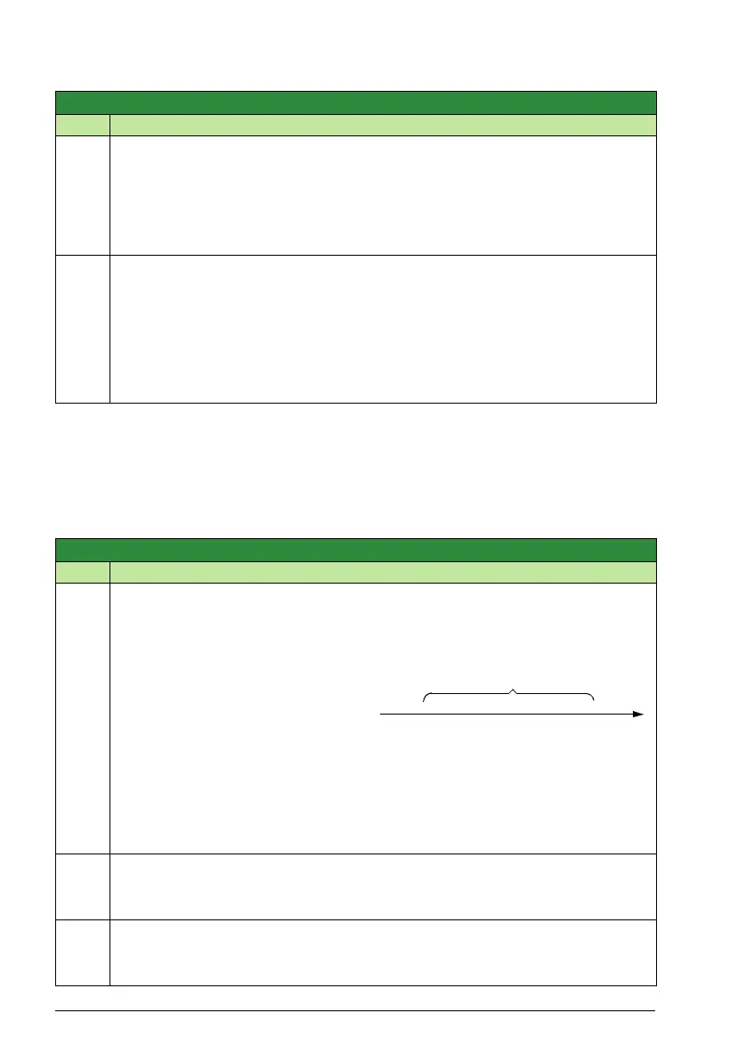
Sets the number of allowed automatic resets within a trial period defined by parameter
3102 TRIAL TIME.
If the number of automatic resets
exceeds this limit (within the trial
time), the drive prevents additional
automatic resets and remains
stopped.
Starting then requires a successful
reset performed from the control panel or from a source selected by parameter
1604 FAULT RESET SEL.
Example: Three faults have occurred in the trial time. The last is reset only if the value
for parameter 3101 NUMBER OF TRIALS is 3 or more.
3102
TRIAL TIME
1.0 … 600.0 s 0.1 s 30.0 s
Sets the time period used for counting and limiting the number of resets.
See parameter 3101 NUMBER OF TRIALS.
3103
DELAY TIME
0.0 … 120.0 s 0.1 s 0.0 s
Sets the delay time between a fault detection and attempted drive restart.
If DELAY TIME = zero, the drive resets immediately.
Group 30: Fault functions
Code Description Range Resolution Default S
XXX
Time
Trial time
x = Automatic reset

Table of Contents

Other manuals for ABB ACS320

Question and Answer IconNeed help?

Do you have a question about the ABB ACS320 and is the answer not in the manual?

ABB ACS320 Specifications

General IconGeneral
Overload Capacity150% for 60 seconds
IP RatingIP20
Frame SizeR1 to R3
Enclosure RatingIP20
Frequency Range0 to 500 Hz
Protection FeaturesOvervoltage, Undervoltage, Overcurrent, Overload, Short circuit, Ground fault, Overtemperature
Fieldbus CommunicationModbus RTU, PROFIBUS DP, CANopen
Communication InterfacesRS485
Operating Temperature-10 to +50 °C (14 to 122 °F)
Storage Temperature-40°C to +70°C
HumidityLess than 95% (non-condensing)
Supply Voltage200 V to 240 V (±10%), 380 V to 480 V (±10%)
Input Voltage200 V to 240 V (±10%), 380 V to 480 V (±10%)

Summary

Safety

Safety in installation and maintenance

General safety rules for drive, motor cable, and motor installation and maintenance.

Electrical safety

Critical electrical safety instructions for qualified electricians, including precautions against electric shock.

General safety

General safety guidelines for installation, start-up, and operation, including warnings about ignoring instructions.

Planning the electrical installation

Implementing the AC power line connection

Specifies requirements for connecting the drive to the AC power line, including leakage current considerations.

Selecting the supply disconnecting device (disconnecting means)

Details the types of disconnecting devices required for different regions and safety standards.

Electrical installation

Checking the insulation of the assembly

Instructions for checking the insulation of the drive, input power cable, and motor/motor cable to ensure safety.

Connecting the power cables

Provides connection diagrams and procedures for safely connecting input power and motor cables, including grounding.

Start-up

Start-up by using the Start-up assistant

Guides users through the step-by-step process of using the Start-up assistant for initial drive configuration.

Application macros

Program features

Start-up assistant

Explains the function of the Start-up assistant in guiding users through initial drive configuration and data entry.

Actual signals and parameters

Fieldbus control

Fault tracing

Alarm and fault indications

Explains how alarms and faults are indicated via LEDs and panel messages, and how to identify causes.

How to reset

Details the methods for resetting faults, including keypad, digital input, fieldbus, or power cycling.

Alarm messages generated by the drive

Lists common alarm messages, their causes, and recommended troubleshooting steps for quick resolution.

Fault messages generated by the drive

Provides a comprehensive list of drive faults, their potential causes, and corrective actions for effective troubleshooting.

Maintenance and hardware diagnostics

Technical data

Ratings

Provides detailed electrical and mechanical ratings for various ACS320 drive types, including input/output currents and frame sizes.

Sizing

Guides users on how to size the drive based on motor current and power, considering ambient temperature and altitude derating.

Fuses and alternate short-circuit protection

Specifies fuse requirements and alternative manual motor protectors for branch circuit protection, ensuring safe operation.

Related product manuals