198 Actual signals and parameters
Group 25: Critical speeds
This group defines up to three critical speeds or ranges of speeds that are to be
avoided due, for example, to mechanical resonance problems at certain speeds.
Group 25: Critical speeds
Code Description Range Resolution Default S
2501
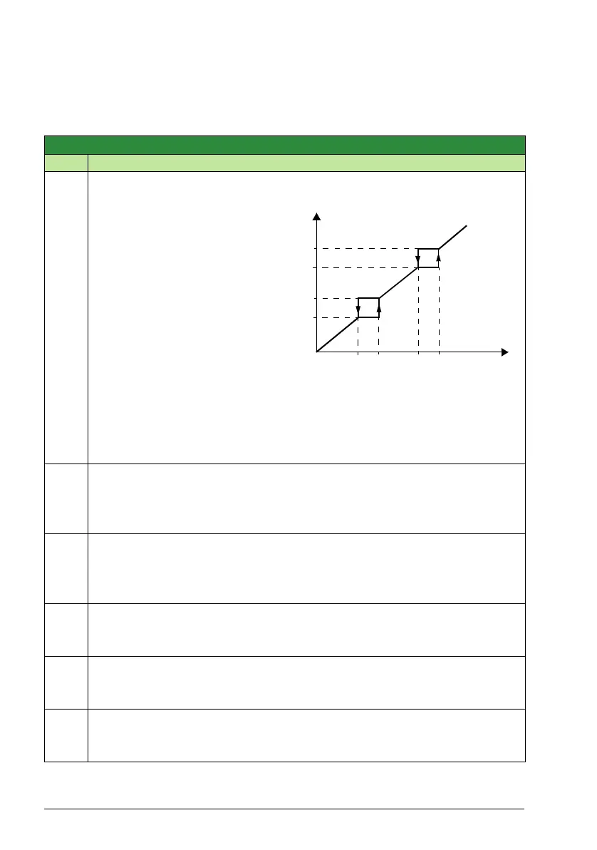
CRIT SPEED SEL
0, 1 1 0
Sets the critical speeds function on or
off. The critical speed function avoids
specific speed ranges.
0 = OFF – Disables the critical speeds
function.
1 = ON – Enables the critical speeds
function.
Example: To avoid speeds at which a
fan system vibrates badly:
• Determine problem speed ranges.
Assume they are found to be:
18…23 Hz and 46…52 Hz.
• Set 2501 CRIT SPEED SEL = 1.
•Set 2502 CRIT SPEED 1 LO = 18
Hz.
•Set 2503 CRIT SPEED 1 HI = 23 Hz.
•Set 2504 CRIT SPEED 2 LO = 46 Hz.
•Set 2505 CRIT SPEED 2 HI = 52 Hz.
2502
CRIT SPEED 1 LO
0.0 … 500.0 Hz 0.1 Hz 0.0 Hz
Sets the minimum limit for critical speed range 1.
• Value must be less than or equal to 2503 CRIT SPEED 1 HI.
• Units are rpm.
2503
CRIT SPEED 1 HI
0.0 … 500.0 Hz 0.1 Hz 0.0 Hz
Sets the maximum limit for critical speed range 1.
• Value must be greater than or equal to 2502 CRIT SPEED 1 LO.
• Units are rpm.
2504
CRIT SPEED 2 LO
0.0 … 500.0 Hz 0.1 Hz 0.0 Hz
Sets the minimum limit for critical speed range 2.
• See parameter 2502 CRIT SPEED 1 LO.
2505
CRIT SPEED 2 HI
0.0 … 500.0 Hz 0.1 Hz 0.0 Hz
Sets the maximum limit for critical speed range 2.
• See parameter 2503 CRIT SPEED 1 HI.
2506
CRIT SPEED 3 LO
0.0 … 500.0 Hz 0.1 Hz 0.0 Hz
Sets the minimum limit for critical speed range 3.
• See parameter 2502 CRIT SPEED 1 LO.
f
output
52
46
23
18
f
REF
(Hz)
f1L
18
f2L
46
f1H
23
f2H
52