306 Fieldbus control
N2 binary input objects
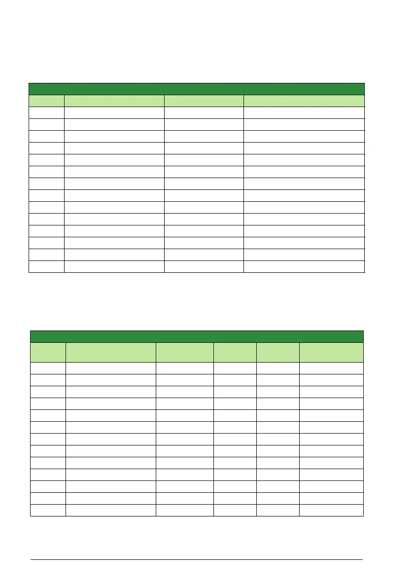
The following table lists the N2 binary input objects defined for the ACS320 drive.
1.Require optional MREL relay output card.
N2 analog output objects
The following table lists the N2 analog output objects defined for the ACS320 drive.
N2 Binary Inputs:
Number Object Drive Parameter Range
BI1 STOP/RUN Status Word 0 = Stop, 1 = Drive Running
BI2 FORWARD/REVERSE Status Word 0 = Forward, 1 = Reverse
BI3 FAULT STATUS Status Word 0 = OK, 1 = Drive Fault
BI16 EXTERNAL 2 SELECT Status Word 0 = EXT1 = EXT2
BI17 HAND/AUTO Status Word 0 = AUTO, 1 = HAND
BI18 ALARM Status Word 0 = OK, 1 = ALARM
BI19 MAINTENANCE REQ Status Word 0 = OK, 1 = MAINT REQ
BI20 DRIVE READY Status Word 0 = Not Ready, 1 = Ready
BI21 AT SETPOINT Status Word 0 = No, 1 = At Setpoint
BI22 RUN ENABLED Status Word 0 = Not Enabled, 1 = Enabled
BI23 N2 LOCAL MODE Status Word 0 = Auto, 1 = N2 Local
BI24 N2 CONTROL SRC Status Word 0 = No, 1 = Yes
BI25 N2 REF1 SRC Status Word 0 = No, 1 = Yes
BI26 N2 REF2 SRC Status Word 0 = No, 1 = Yes
N2 Analog Outputs:
Number Object
Drive
Parameter
Scale
Factor
Units Range
AO1 REFERENCE 1 Reference 1 10 % 0…100
AO2 REFERENCE 2 Reference 2 10 % 0…100
AO3 ACCEL TIME 1 2202 10 s 0.1…1800
AO4 DECEL TIME 1 2203 10 s 0.1…1800
AO5 CURRENT LIMIT 2003 10 A 0…1.3*I
2N
AO6 PID1-CONT GAIN 4001 10 % 0.1…100
AO7 PID1-CONT I-TIME 4002 10 s 0.1…600
AO8 PID1-CONT D-TIME 4003 10 s 0…10
AO9 PID1-CONT D FILTER 4004 10 s 0…10
AO10 PID2-CONT GAIN 4101 10 % 0.1…100
AO11 PID2-CONT I-TIME 4102 10 s 0.1…600
AO12 PID2-CONT D-TIME 4103 10 s 0…10
AO13 PID2-CONT D FILTER 4104 10 s 0…10

 Loading...


