50 Electrical installation
Connecting the control cables
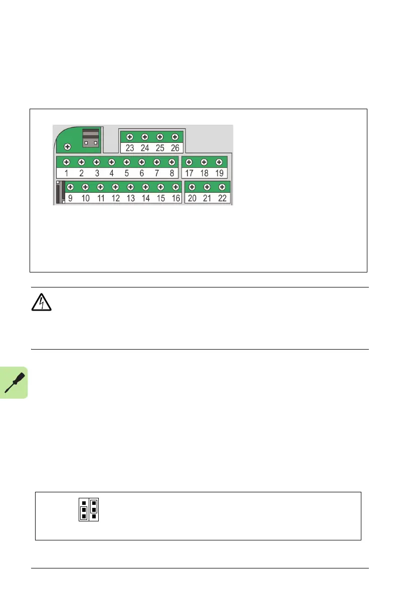
I/O terminals
The figure below shows the I/O terminals. Tightening torque is 0.4 N·m / 3.5 in-lb.
WARNING! All ELV (Extra Low Voltage) circuits connected to the drive must be
used within a zone of equipotential bonding, in other words, within a zone
where all simultaneously accessible conductive parts are electrically connected to
prevent hazardous voltages appearing between them. This is accomplished by a
proper factory grounding.
The terminals on the control board as well as on the optional modules attachable to
the board fulfill the Protective Extra Low Voltage (PELV) requirements stated in EN
50178, provided that the external circuits connected to the terminals also fulfill the
requirements and the installation site is below 2000 m (6562 ft).
Voltage and current selection for analog inputs
Jumper S1 selects voltage (0 [2]…10 V / -10…10 V) or current (0 [4]…20 mA /
-20…20 mA) as the signal types for analog inputs AI1 and AI2. The factory settings
are unipolar voltage for AI1 (0 [2]…10 V) and unipolar current for AI2 (0 [4]…20 mA),
which correspond to the default usage in the application macros. The jumper is
located to the left of I/O terminal 9 (see the I/O terminal figure above).
Permanently affix control cables with a minimum 1/4" spacing from power cables.
X1A:
1: SCR
2: AI1
3: GND
4: +10 V
5: AI2
6: GND
7: AO
8: GND
9: +24 V
10: GND
11: DCOM
12: DI1
13: DI2
14: DI3
15: DI4
16: DI5 digital or frequency input
X1B:
17: ROCOM
18: RONC
19: RONO
20: DOSRC
21: DOOUT
22: DOGND
X1C:
23: SCR
24: B
25: A
26: GND_A
mA
V
S1
X1A X1B
X1CJ701
AI1
AI2
J701: Connects 120 ohm termination resistor. See page
55.
S1: Selects voltage or current as the signal types for
analog inputs AI1 and AI2.
AI1
AI2
Top position: I (0 [4]…20 mA, default for AI2; or -20…20 mA)
Bottom position: U (0 [2]…10 V, default for AI1; or -10…10 V)
S1

 Loading...


