Actual signals and parameters 173
Group 13: Analogue inputs
This group defines the limits and the filtering for analog inputs.
Group 13: Analogue inputs
Code Description Range Resolution Default S
1301
MINIMUM AI1
-100.0 … 100.0% 0.1% 20.0%
Defines the minimum value of the analog input.
• Define value as a percent of the full analog signal range. See example below.
• The minimum analog input signal corresponds to parameter 1104 REF1 MIN or
1107 REF2 MIN.
• MINIMUM AI cannot be greater than MAXIMUM AI.
• These parameters (reference and analog min. and max. settings) provide scale and
offset adjustment for the reference.
• See figure at parameter 1104 REF1 MIN.
Example: To set the minimum analog input value to 4 mA:
• Configure the analog input for 0 … 20 mA current signal.
• Calculate the minimum (4 mA) as a percent of full range
(20 mA) = 4 mA / 20 mA * 100% = 20%
1302
MAXIMUM AI1
-100.0 … 100.0% 0.1% 20.0%
Defines the maximum value of the analog input.
• Define value as a percent of the full analog signal range.
• The maximum analog input signal corresponds to 1105 REF1 MAX or 1108 REF2
MAX.
• See figure at parameter 1104 REF1 MIN.
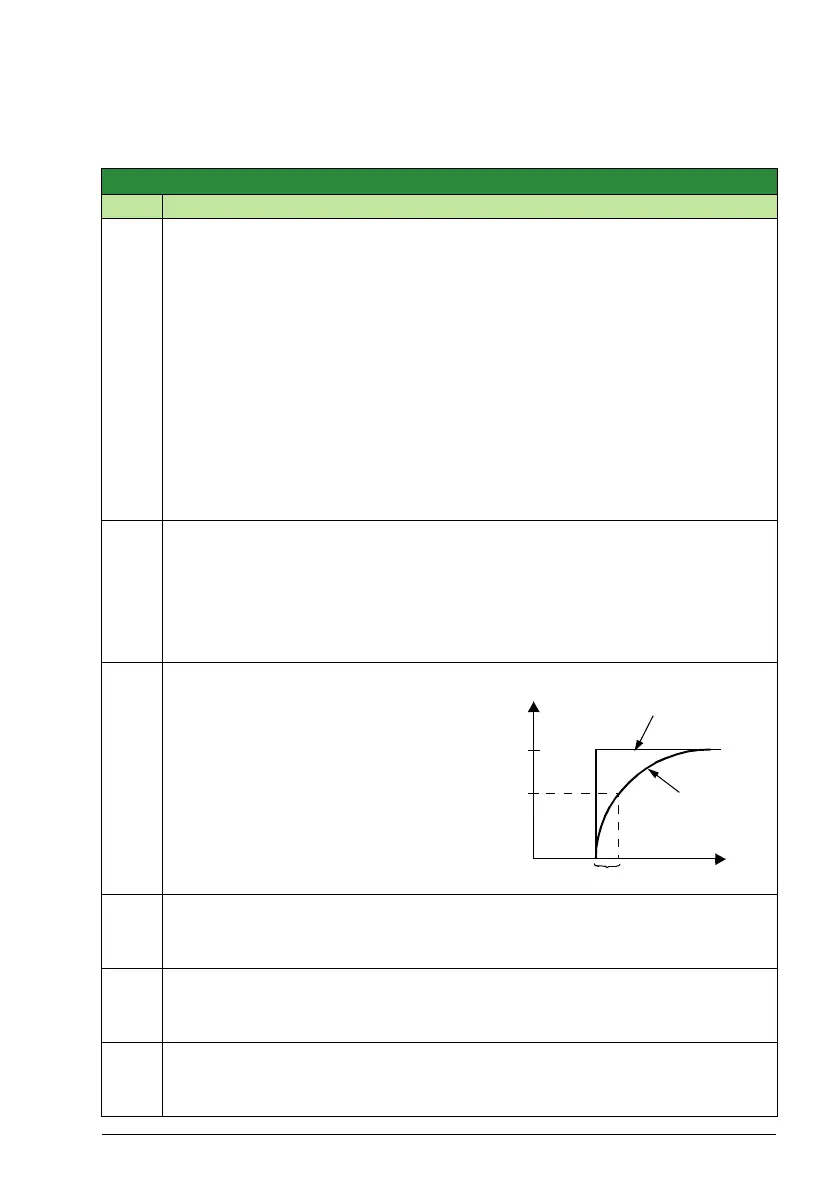
1303
FILTER AI1
0.0 … 10.0 s 0.1 s 0.1 s
Defines the filter time constant for analog
input 1 (AI1).
• The filtered signal reaches 63% of a step
change within the time specified.
1304
MINIMUM AI2
100.0 … 100.0% 0.1% 20.0%
Defines the minimum value of the analog input.
• See parameter 1301 MINIMUM AI1 above.
1305
MAXIMUM AI2
-100.0 … 100.0% 0.1% 100.0%
Defines the maximum value of the analog input.
• See parameter 1302 MAXIMUM AI1 above.
1306
FILTER AI2
0.0 … 10.0 s 0.1 s 0.1 s
Defines the filter time constant for analog input 2 (AI2).
• See parameter 1303 FILTER AI1 above
100
63
%
t
Unfiltered signal
Filtered signal
Time constant