258 Actual signals and parameters
Group 64: Load analyzer
This group defines the settings for the load analyzing function for peak value and
amplitude. See section Load analyzer on page 136.
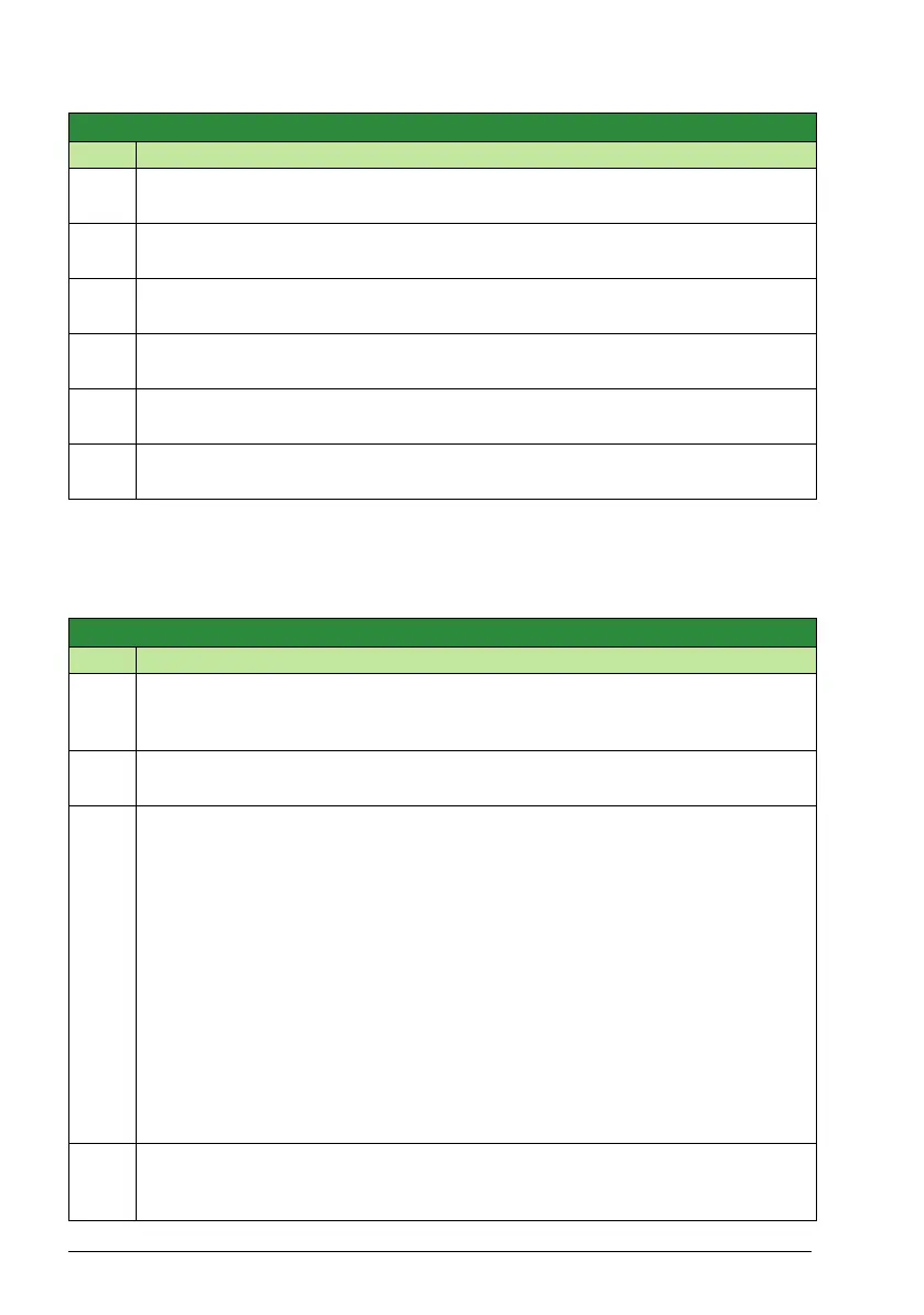
5327
MDB DATA OUT 5
0…9999 1 0
Modbus register 40084 - Write only. Supported by STD Modbus only.
5328
MDB DATA OUT 6
0…9999 1 0
Modbus register 40085 - Write only. Supported by STD Modbus only.
5329
MDB DATA OUT 7
0…9999 1 0
Modbus register 40086 - Write only. Supported by STD Modbus only.
5330
MDB DATA OUT 8
0…9999 1 0
Modbus register 40087 - Write only. Supported by STD Modbus only.
5331
MDB DATA OUT 9
0…9999 1 0
Modbus register 40088 - Write only. Supported by STD Modbus only.
5332
MDB DATA OUT 10
0…9999 1 0
Modbus register 40089 - Write only. Supported by STD Modbus only.
Group 64: Load analyzer
Code Description Range Resolution Default S
6401
PVL SIGNAL
101…178 103
Defines the signal logged for peak value. Parameter index in
Group 01: Operating data. For example, 102 = 0102 SPEED.
6402
PVL FILTER TIME
0.0 … 120.0 s 1 = 0.1 s 0.1 s
Defines the filter time for peak value logging. Filter time
6403
LOGGERS RESET
NOT SEL
Defines the source for the reset of loggers.
0 = NOT SEL – No reset selected.
1 = DI1 – Reset loggers on the rising edge of DI1.
2 = DI2 – See selection DI1.
3 = DI3 – See selection DI1.
4 = DI4 – See selection DI1.
5 = DI5 – See selection DI1.
7 = RESET – Reset loggers. Parameter is set to NOT SEL.
-1 = DI1(INV) – Reset loggers on the falling edge of DI1.
-2 = DI2(INV) – See selection DI1(INV).
-3 = DI3(INV) – See selection DI1(INV).
-4 = DI4(INV) – See selection DI1(INV).
-5 = DI5(INV) – See selection DI1(INV).
6404
AL2 SIGNAL
101…178 103
Defines the signal logged for amplitude logger 2. Parameter index in Group 01:
Operating data. For example, 102 = 0102 SPEED.
Group 53: EFB protocol
Code Description Range Resolution Default S

 Loading...


