Actual signals and parameters 213
Group 34: Panel display
This group defines the content for control panel display (middle area), when the
control panel is in the Output mode.
Group 34: Panel display
Code Description Range Resolution Default S
3401
SIGNAL1 PARAM
101…178 1 103
Selects the first parameter (by number)
displayed on the control panel.
• Definitions in this group define display
content when the control panel is in the
Output mode.
•Any Group 01: Operating data
parameter number can be selected.
• Using the following parameters, the
display value can be scaled, converted
to convenient units, and/or displayed as a bar graph.
• The figure identifies selections made by parameters in this group.
100 = not selected – First parameter not displayed.
101…199 = Displays parameter 0101…0199. If parameter does not exist, the display
shows “n.a.”.
3402
SIGNAL1 MIN
Depends on selection 0.0
Defines the minimum expected value for
the first display parameter.
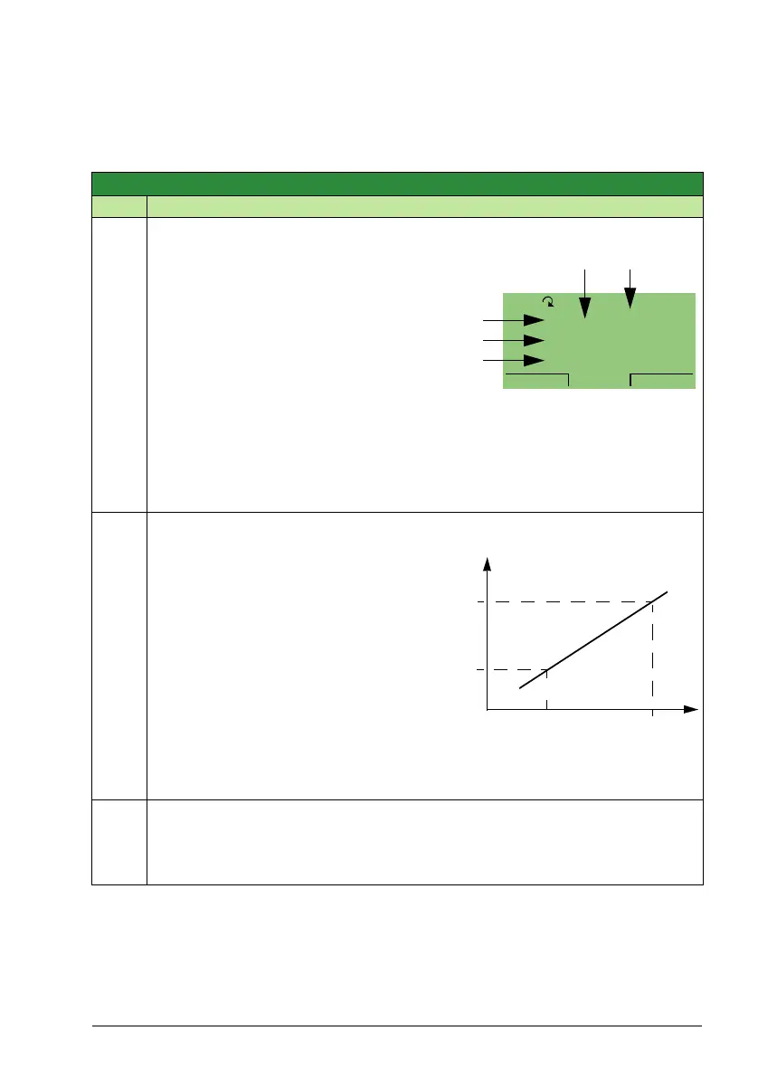
Use parameters 3402, 3403, 3406, and
3407, for example to convert a Group 01
parameter, such as 0102 SPEED (in rpm)
to the speed of a conveyor driven by the
motor (in ft/min). For such a conversion,
the source values in the figure are the min.
and max. motor speed, and the display
values are the corresponding min. and
max. conveyor speed. Use parameter
3405 to select the proper units for the
display.
Note: Selecting units does not convert values.
3403
SIGNAL1 MAX
Depends on selection - 600.0
Defines the maximum expected value for the first display parameter.
Note: Parameter is not effective if parameter 3404 OUTPUT1 DSP FORM = 9
(DIRECT).
7 A
0 %
8 mA8.
3.
30.
15.0Hz
AUTO
MENU00:00
0137
0138
0139
3404 3405
Source value
Display
value
3407
3406
3402 3403

 Loading...


