88 Application macros
Booster pump
This macro configures for booster pump applications where the pump speed is
controlled according to a signal received from a transducer. When using direct speed
reference in AUTO mode or process PID, see General considerations on page 80.
For more information see Default values with different macros on page 279.
Parameters changed relative to HVAC default
Parameter Value
9902 APPLIC MACRO 6 (BOOSTER PUMP)
2101 START FUNCTION 1 (AUTO)
2202 ACCELER TIME 1 10.0 s
2203 DECELER TIME 1 10.0 s
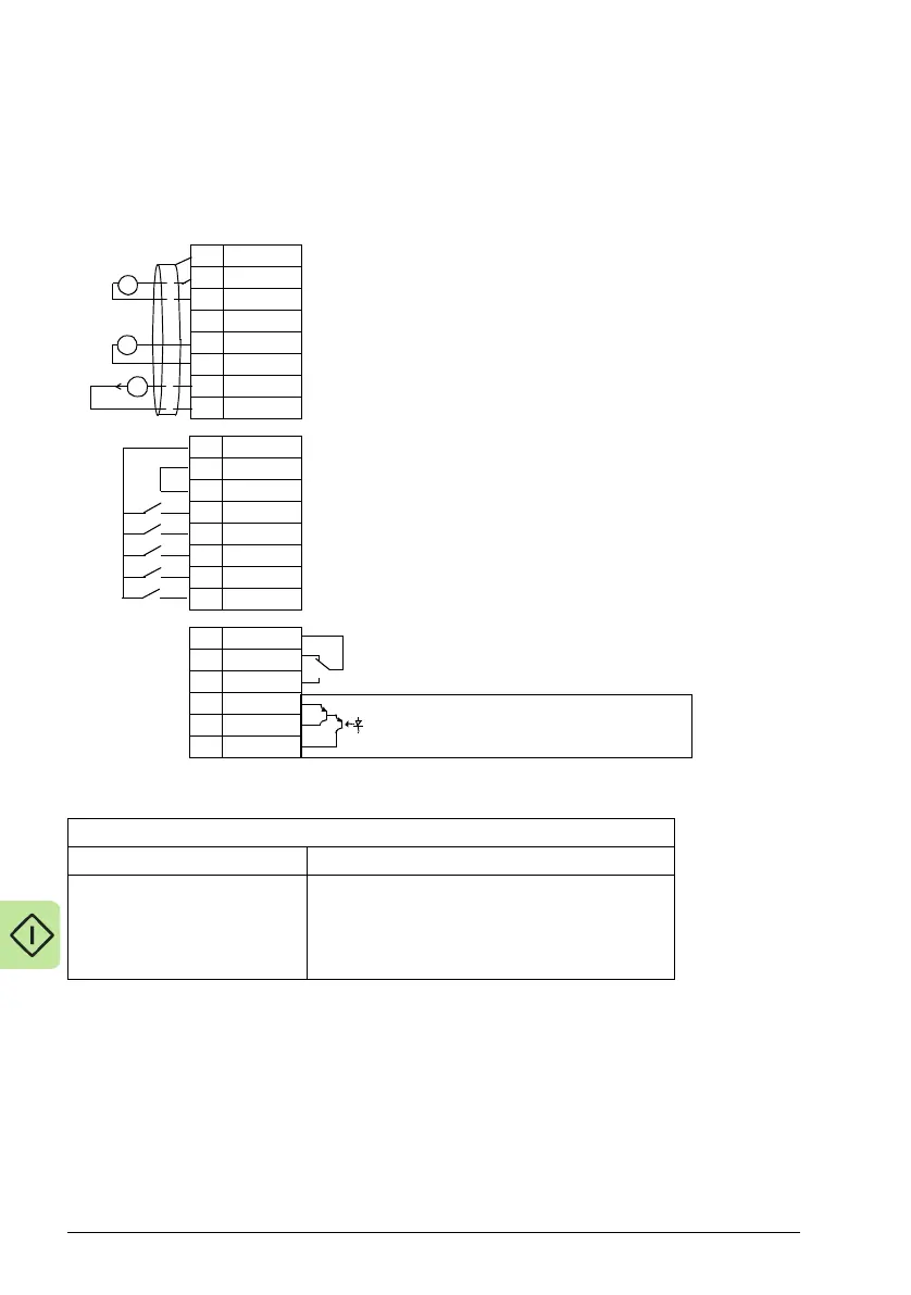
1SCR
2AI1
3AGND
410V
5AI2
6AGND
7AO1
8AGND
924V
10 GND
11 DCOM
12 DI1
13 DI2
14 DI3
15 DI4
16 DI5
17 RO1C
18 RO1A
19 RO1B
20 DOSRC
21 DOOUT
22 DOGND
External reference 0(2)…10 V or 0(4)…20 mA
Reference voltage 10 VDC
Output frequency: 0(4)…20 mA
Start/Stop: Activate to start drive
Run permissive: Deactivate to stop drive (P 1601)
Constant (Preset) speed 1 (P 1202)
Safety interlock1: Deactivate to stop drive (P 1608)
Safety interlock2: Deactivate to stop drive (P 1609)
Relay output 1 (P 1401)
Default operation: Started =>17 connected to 19
Digital output, max. 100 mA (P 1805)
No fault [Fault(-1)] =>20 connected to 22
X1A
Analog input circuit common
PID feedback: 0(2)…10 V or 0(4)…20 mA
Analog output circuit common
Auxiliary voltage output +24 VDC
Auxiliary voltage output common
Digital input common for all
Signal cable shield (screen)
Analog input circuit common
+
mA
+
X1B

 Loading...


