7-
2
750/760 Feeder Management Relay GE Power Management
7.2 SETPOINT ENTRY METHODS 7 SETPOINTS
7
7.2 SETPOINT ENTRY METHODS 7.2.1 DESCRIPTION
Prior to operating the relay on a feeder, setpoints defining system characteristics, inputs, relay outputs, and
protection settings must be entered, via one of the following methods:
1. Front panel, using the keys and display.
2. Front program port, and a portable computer running the 750/760 PC program supplied with the relay.
3. Rear RS485/RS422 COM1 port or RS485 COM2 port and a SCADA system running user-written software.
Any of these methods can be used to enter the same information. A computer, however, makes entry much
easier. Files can be stored and downloaded for fast, error free entry when a computer is used. To facilitate this
process, a CD with the programming software 750/760 PC program is supplied with the relay.
The relay leaves the factory with setpoints programmed to default values, and it is these values that
are shown in all the setpoint message illustrations
. Many of these factory default values can be left
unchanged.
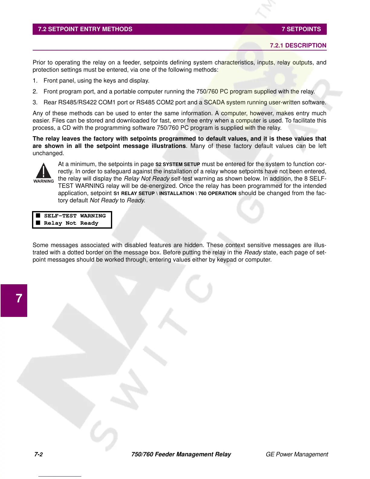
At a minimum, the setpoints in page
S2 SYSTEM SETUP
must be entered for the system to function cor-
rectly. In order to safeguard against the installation of a relay whose setpoints have not been entered,
the relay will display the
Relay Not Ready
self-test warning as shown below. In addition, the 8 SELF-
TEST WARNING relay will be de-energized. Once the relay has been programmed for the intended
application, setpoint
S1 RELAY SETUP \ INSTALLATION \ 760 OPERATION
should be changed from the fac-
tory default
Not Ready
to
Ready
.
Some messages associated with disabled features are hidden. These context sensitive messages are illus-
trated with a dotted border on the message box. Before putting the relay in the
Ready
state, each page of set-
point messages should be worked through, entering values either by keypad or computer.
■ SELF-TEST WARNING
■ Relay Not Ready
WARNING
 Loading...


