GE Power Management 750/760 Feeder Management Relay 6
-
11
6 ACTUAL VALUES 6.3 A2 METERING
6
6.3.6 POWER
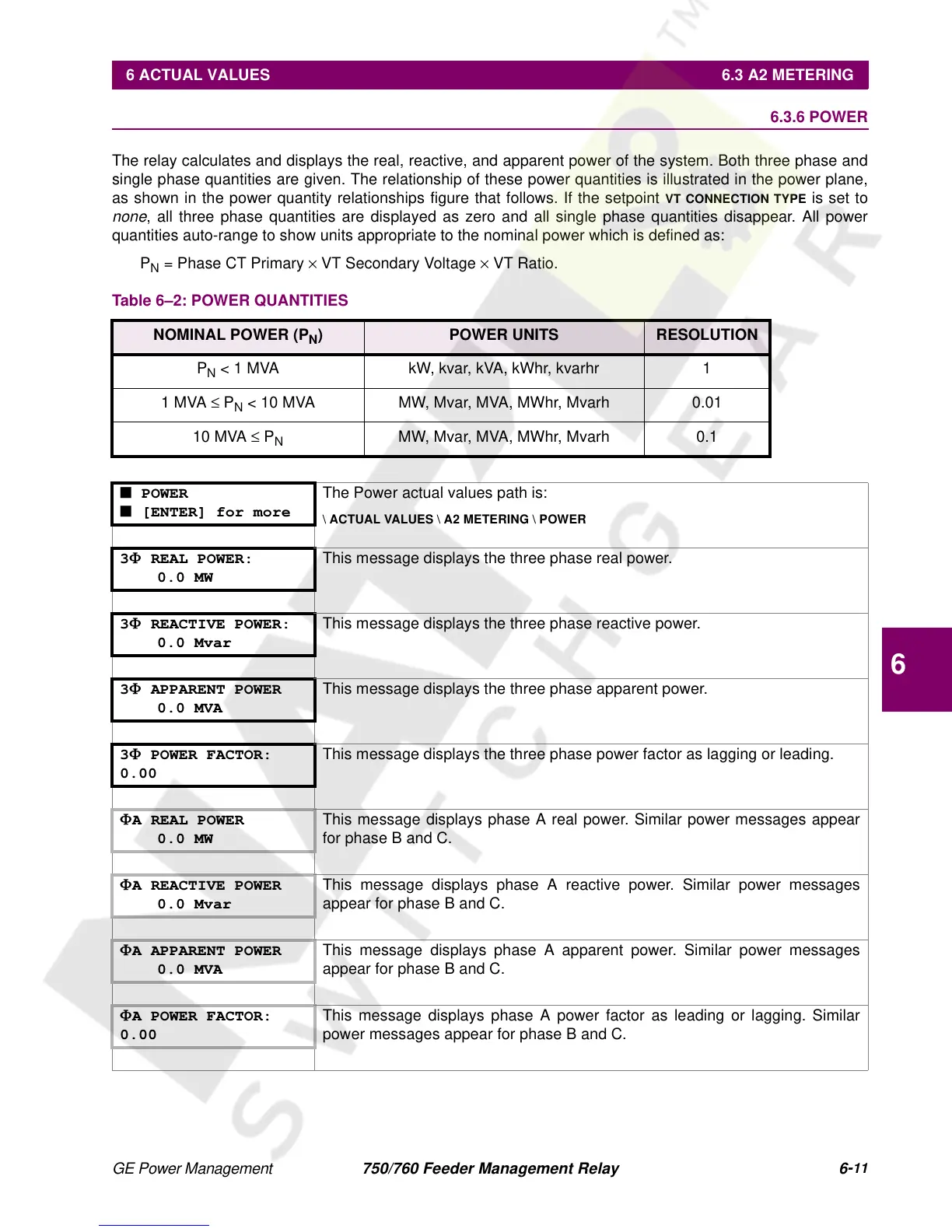
The relay calculates and displays the real, reactive, and apparent power of the system. Both three phase and
single phase quantities are given. The relationship of these power quantities is illustrated in the power plane,
as shown in the power quantity relationships figure that follows. If the setpoint
VT CONNECTION TYPE
is set to
none
, all three phase quantities are displayed as zero and all single phase quantities disappear. All power
quantities auto-range to show units appropriate to the nominal power which is defined as:
P
N
= Phase CT Primary
×
VT Secondary Voltage
×
VT Ratio.
Table 6–2: POWER QUANTITIES
NOMINAL POWER (P
N
) POWER UNITS RESOLUTION
P
N
< 1 MVA kW, kvar, kVA, kWhr, kvarhr 1
1 MVA
≤
P
N
< 10 MVA MW, Mvar, MVA, MWhr, Mvarh 0.01
10 MVA
≤
P
N
MW, Mvar, MVA, MWhr, Mvarh 0.1
■ POWER
■ [ENTER] for more
The Power actual values path is:
\ ACTUAL VALUES \ A2 METERING \ POWER
3
Φ
REAL POWER:
0.0 MW
This message displays the three phase real power.
3
Φ
REACTIVE POWER:
0.0 Mvar
This message displays the three phase reactive power.
3
Φ
APPARENT POWER
0.0 MVA
This message displays the three phase apparent power.
3
Φ
POWER FACTOR:
0.00
This message displays the three phase power factor as lagging or leading.
Φ
A REAL POWER
0.0 MW
This message displays phase A real power. Similar power messages appear
for phase B and C.
Φ
A REACTIVE POWER
0.0 Mvar
This message displays phase A reactive power. Similar power messages
appear for phase B and C.
Φ
A APPARENT POWER
0.0 MVA
This message displays phase A apparent power. Similar power messages
appear for phase B and C.
Φ
A POWER FACTOR:
0.00
This message displays phase A power factor as leading or lagging. Similar
power messages appear for phase B and C.
 Loading...


