12-
2
750/760 Feeder Management Relay GE Power Management
12.1 TIME OVERCURRENT CURVE CHARACTERISTICS 12 S5 PROTECTION
12
Graphs of standard time-current curves on 11”
×
17” log-log graph paper are available upon
request. Requests may be placed with our literature department.
12.1.2 DEFINITE TIME CURVE
The Definite Time curve shape causes a trip as soon as the pickup level is exceeded for a specified period of
time. The base Definite Time curve has a delay of 0.1 seconds. The curve multiplier makes this delay adjust-
able from 0.00 to 10.00 seconds in steps of 0.01 seconds.
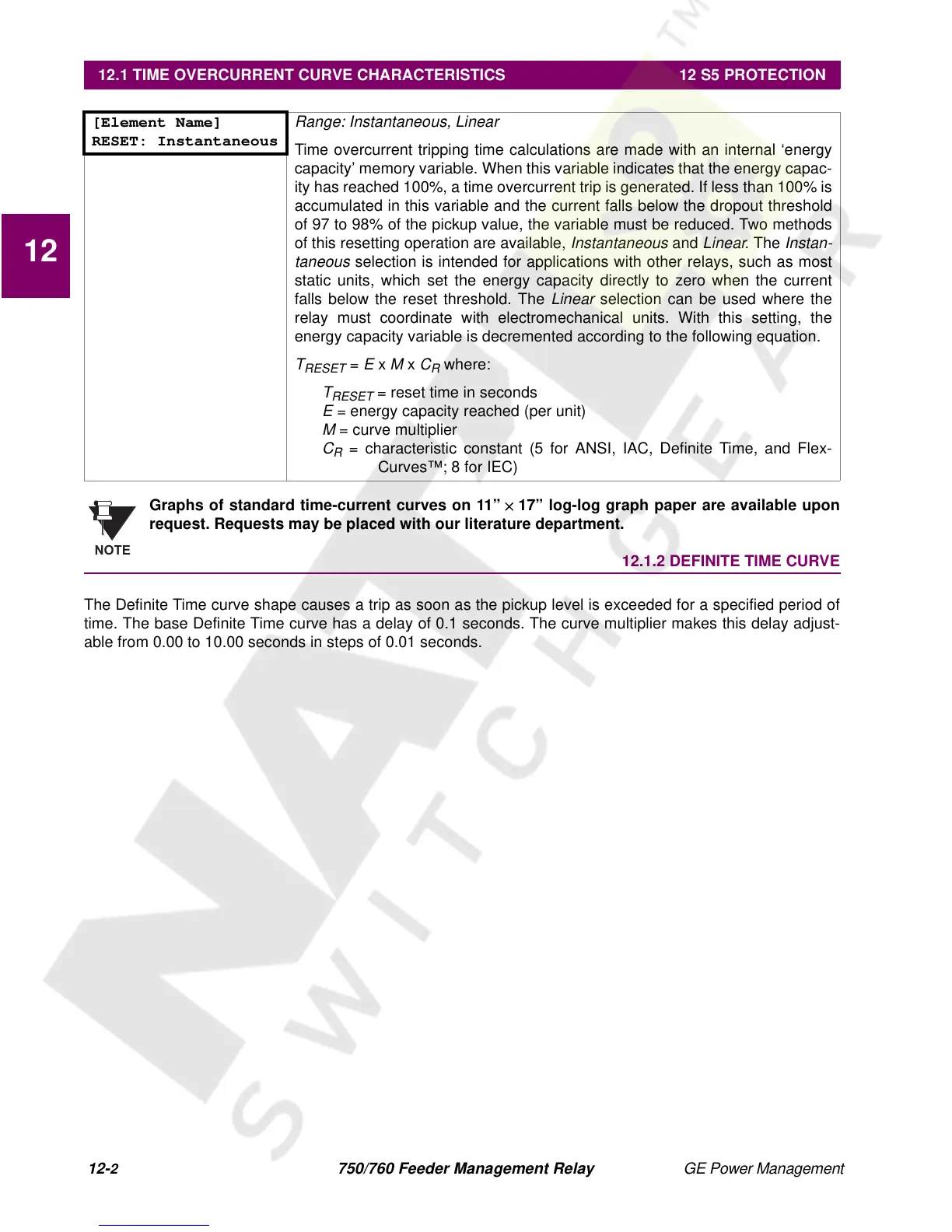
[Element Name]
RESET: Instantaneous
Range: Instantaneous, Linear
Time overcurrent tripping time calculations are made with an internal ‘energy
capacity’ memory variable. When this variable indicates that the energy capac-
ity has reached 100%, a time overcurrent trip is generated. If less than 100% is
accumulated in this variable and the current falls below the dropout threshold
of 97 to 98% of the pickup value, the variable must be reduced. Two methods
of this resetting operation are available,
Instantaneous
and
Linear
. The
Instan-
taneous
selection is intended for applications with other relays, such as most
static units, which set the energy capacity directly to zero when the current
falls below the reset threshold. The
Linear
selection can be used where the
relay must coordinate with electromechanical units. With this setting, the
energy capacity variable is decremented according to the following equation.
T
RESET
=
E
x
M
x
C
R
where:
T
RESET
= reset time in seconds
E
= energy capacity reached (per unit)
M
= curve multiplier
C
R
= characteristic constant (5 for ANSI, IAC, Definite Time, and Flex-
Curves™; 8 for IEC)
NOTE
 Loading...


